MoiréShade
Adaptive Shading Device | 2021
Biomimicry · Physical Model Testing · Environmental Analysis
Ecology & Biology in Architecture
Abstract
MoiréShade is a transforming shading device developed through a series of iterative physical models, drawing on the adaptive stem geometry of the dragon fruit cactus (Hylocereus undatus). Within the tradition of ecologically inspired architecture, the project translates a dragon fruit stem's passive solar management strategy into an architectural surface system. The stem of the dragon fruit has evolved a Y-shaped cross-section that regulates solar exposure across the day; MoiréShade extracts this mechanism and develops it through four successive model tests, moving from a direct geometric translation to a computationally refined, wave-deformed double-surface system. The outcome is a facade device capable of continuously modulating light transmission and solar shading in response to the position of the sun.
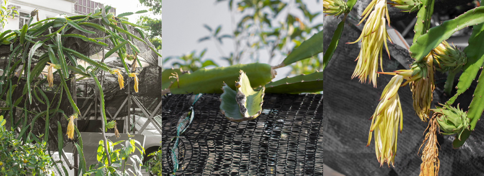
Dragon Fruit Transformation
The dragon fruit cactus (Hylocereus undatus) has evolved a distinctive three-lobed stem geometry as a passive survival strategy in high-radiation environments. Each stem segment functions as an integrated shading device: its Y-shaped cross-section and angled ribs orient themselves to regulate solar exposure throughout the day, maximizing photosynthesis in the morning while deflecting intense midday radiation. At the cellular scale, helically wound cellulose microfibrils within the stem wall provide the structural resilience that enables this adaptive response. MoiréShade translates this biological logic directly into an architectural surface system.
Stem Cross-Section & Surface Transformation
The three-winged rib of the dragon fruit stem is the generative unit of MoiréShade. Viewed in cross-section, each rib extends from a central spine at roughly 120° intervals, producing a Y-shaped profile. When arrayed linearly along the stem, this cross-section traces a continuous adaptive surface. The diagram below shows the translation from the biological cross-section to a modular shading element: the Y-shape is unfolded, regularized, and arrayed into a planar grid, forming the basis for the physical model series.
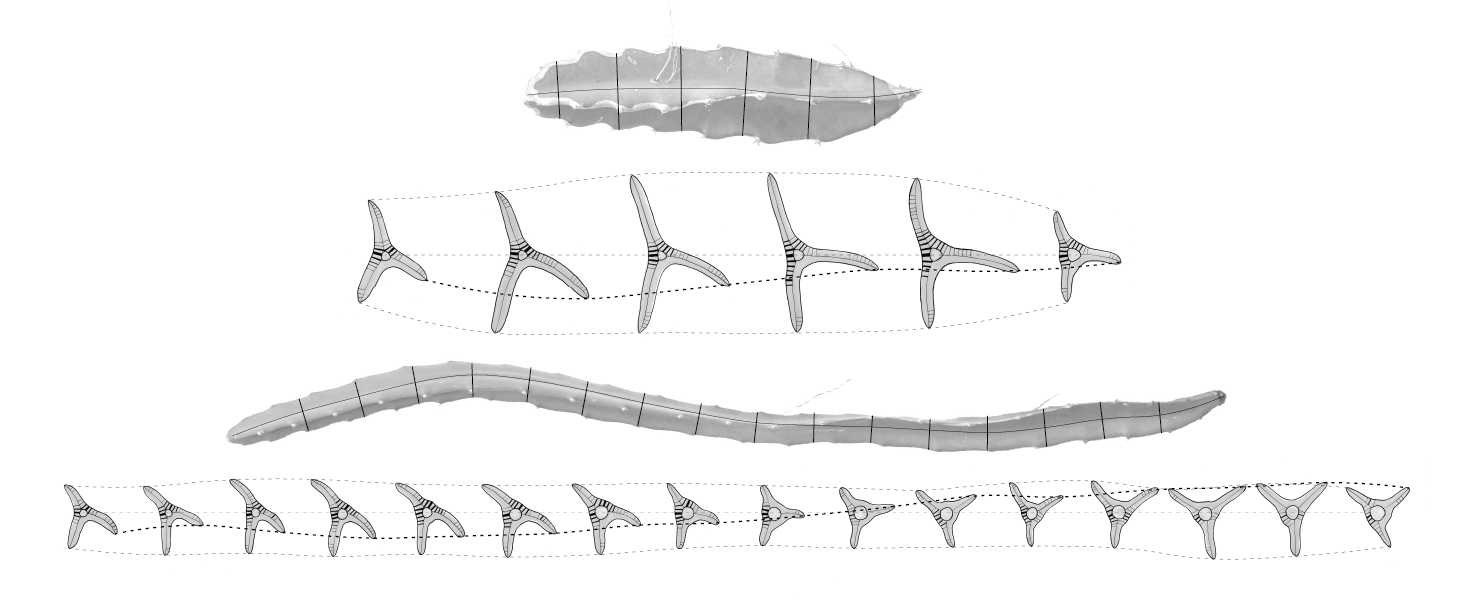
3D rib geometry — Y-shaped cross-section
Cellulose microfibril structure — stem wall
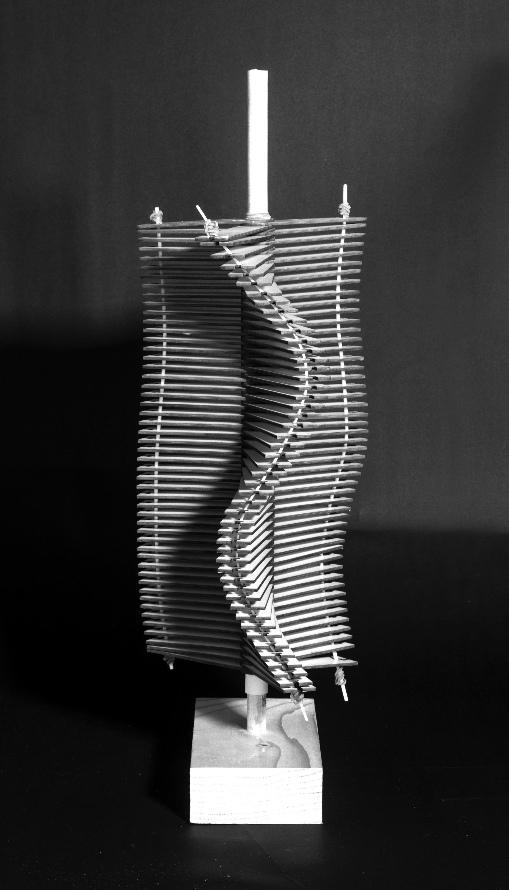
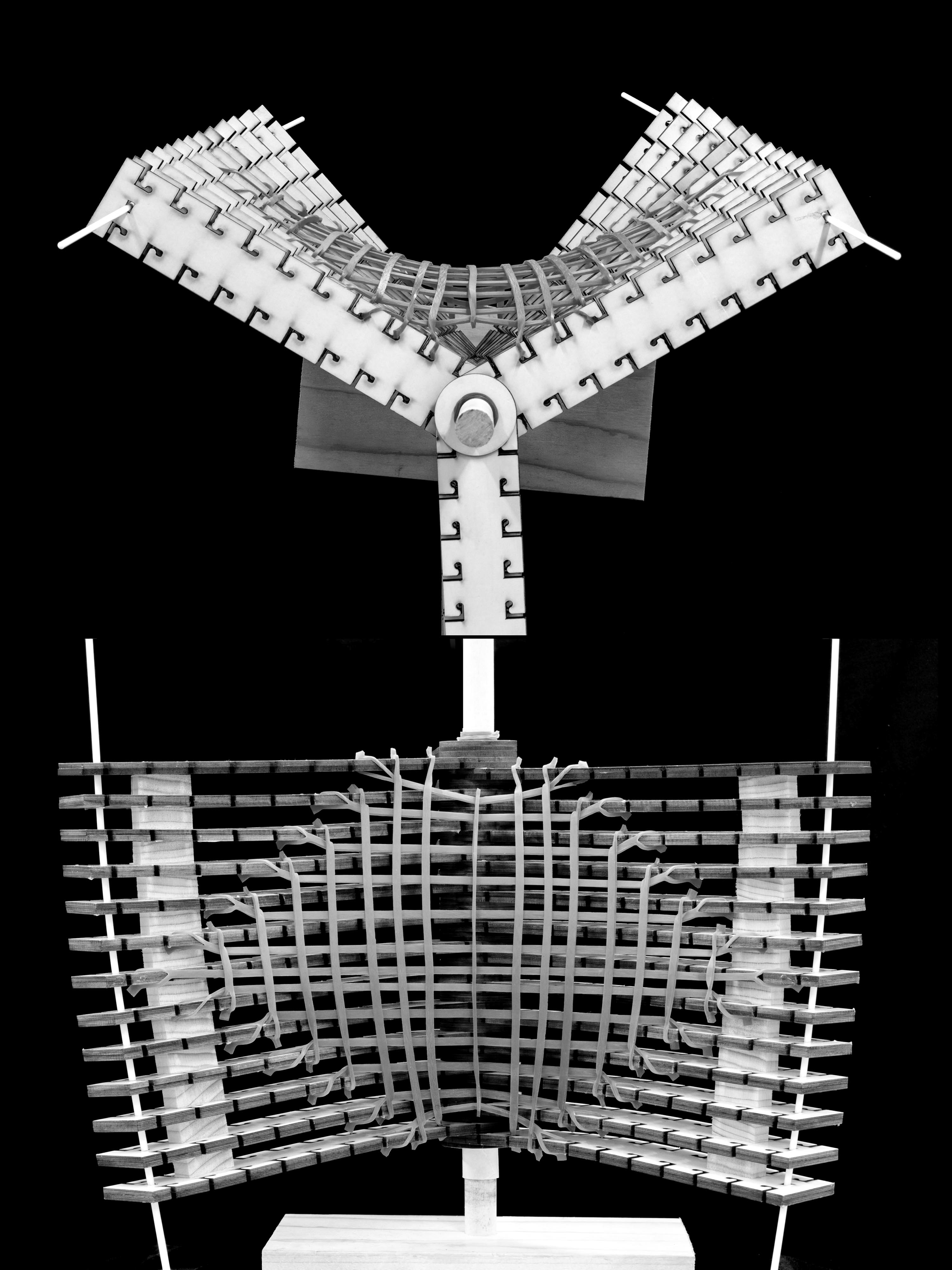
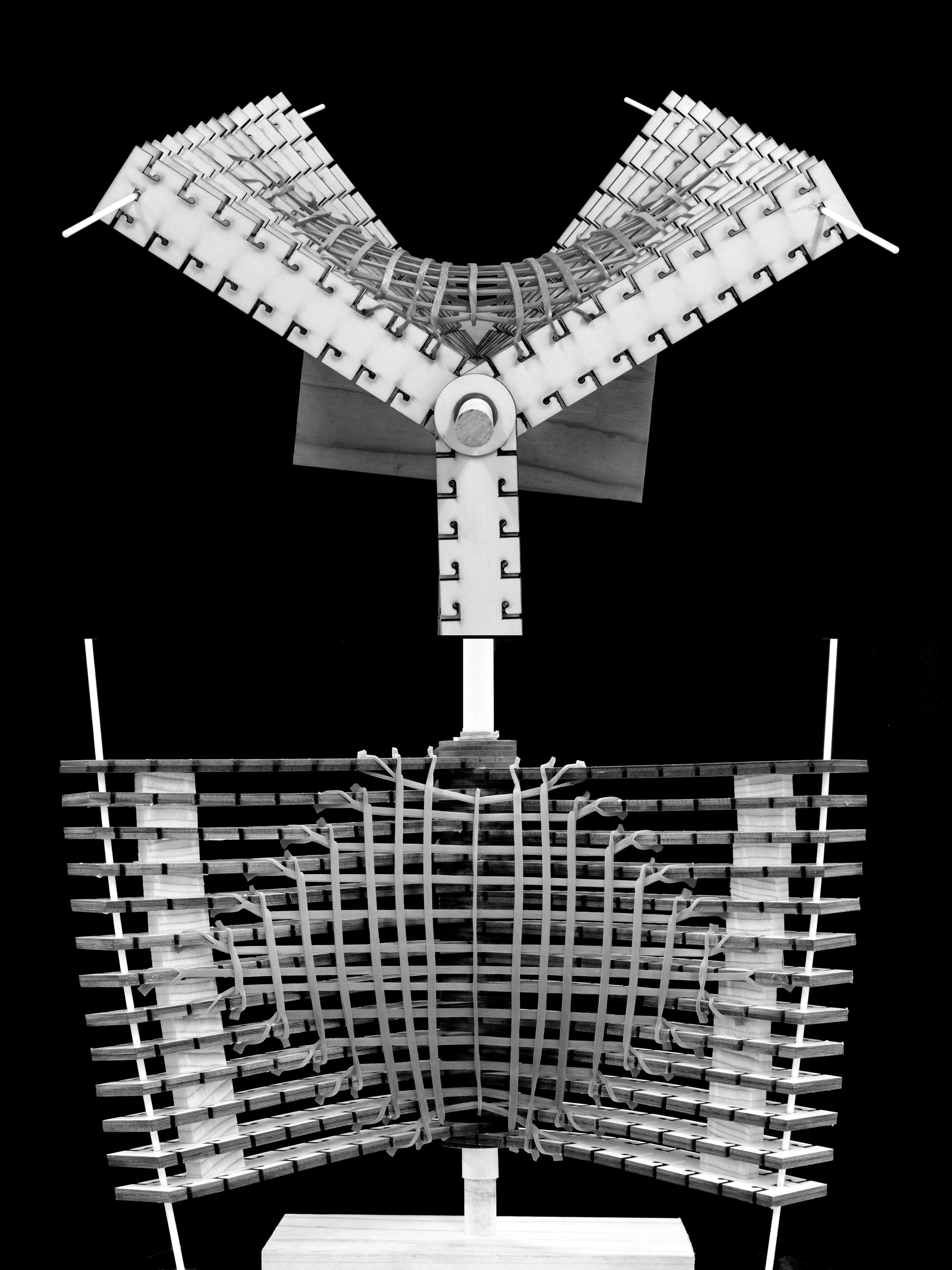
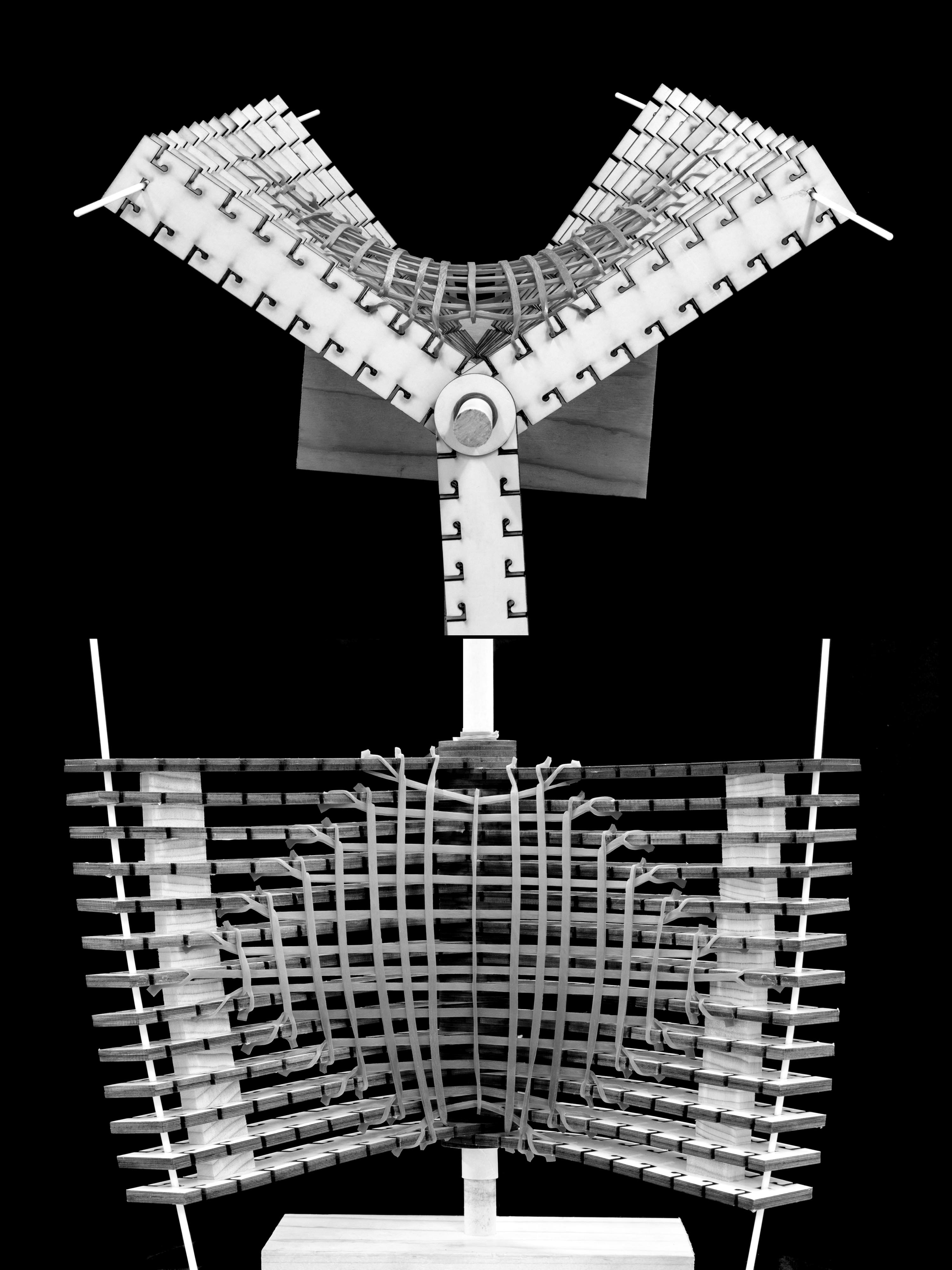
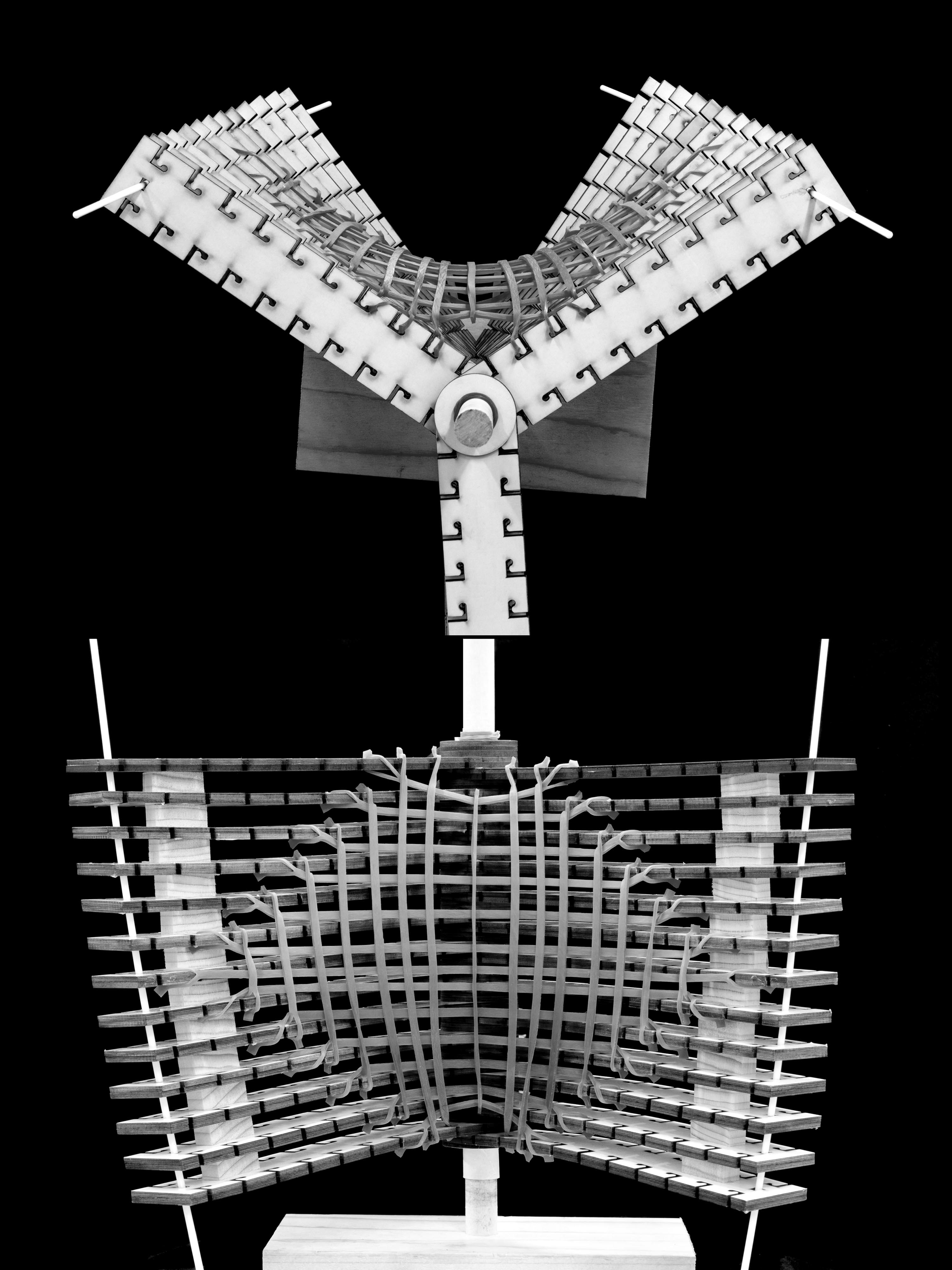
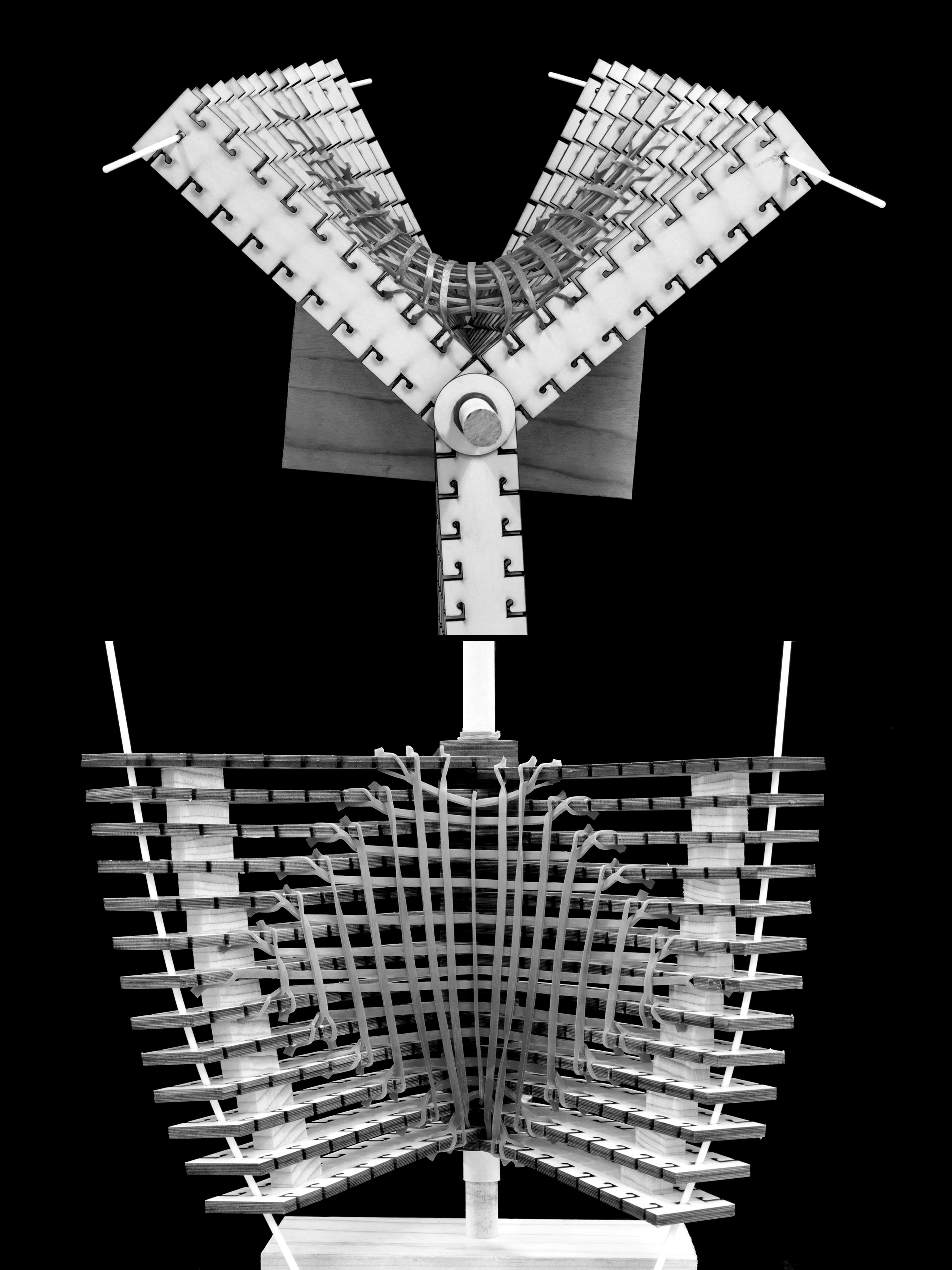
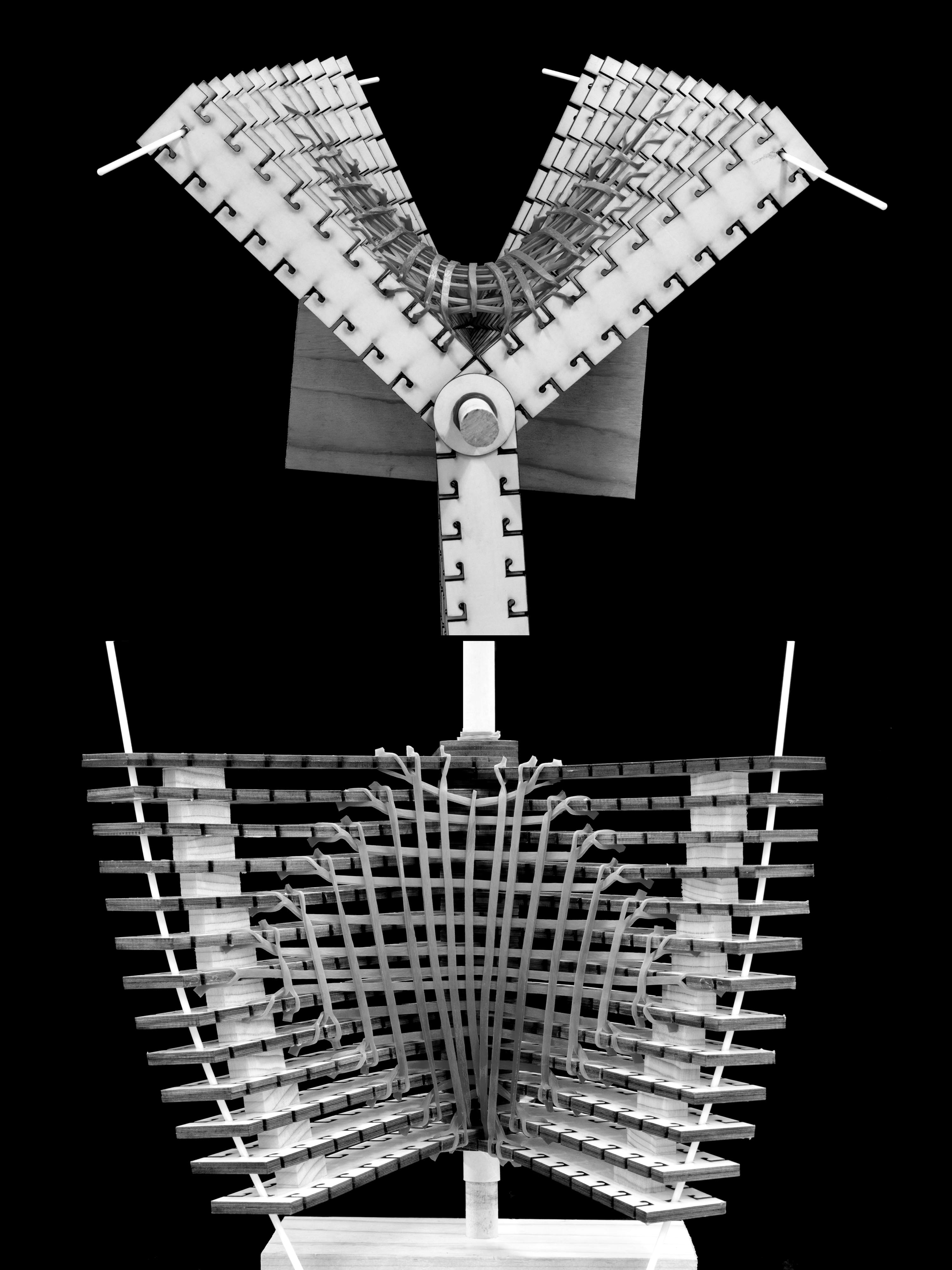
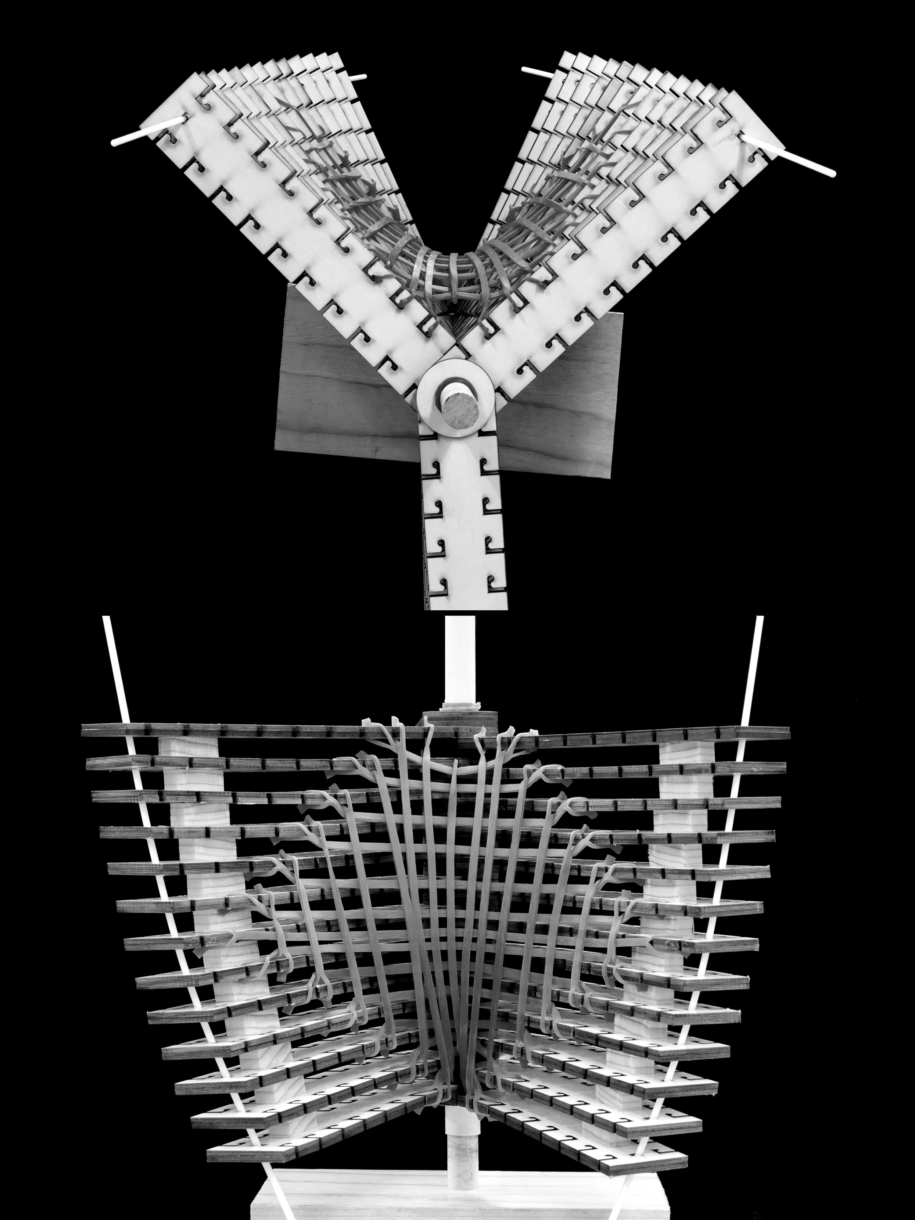
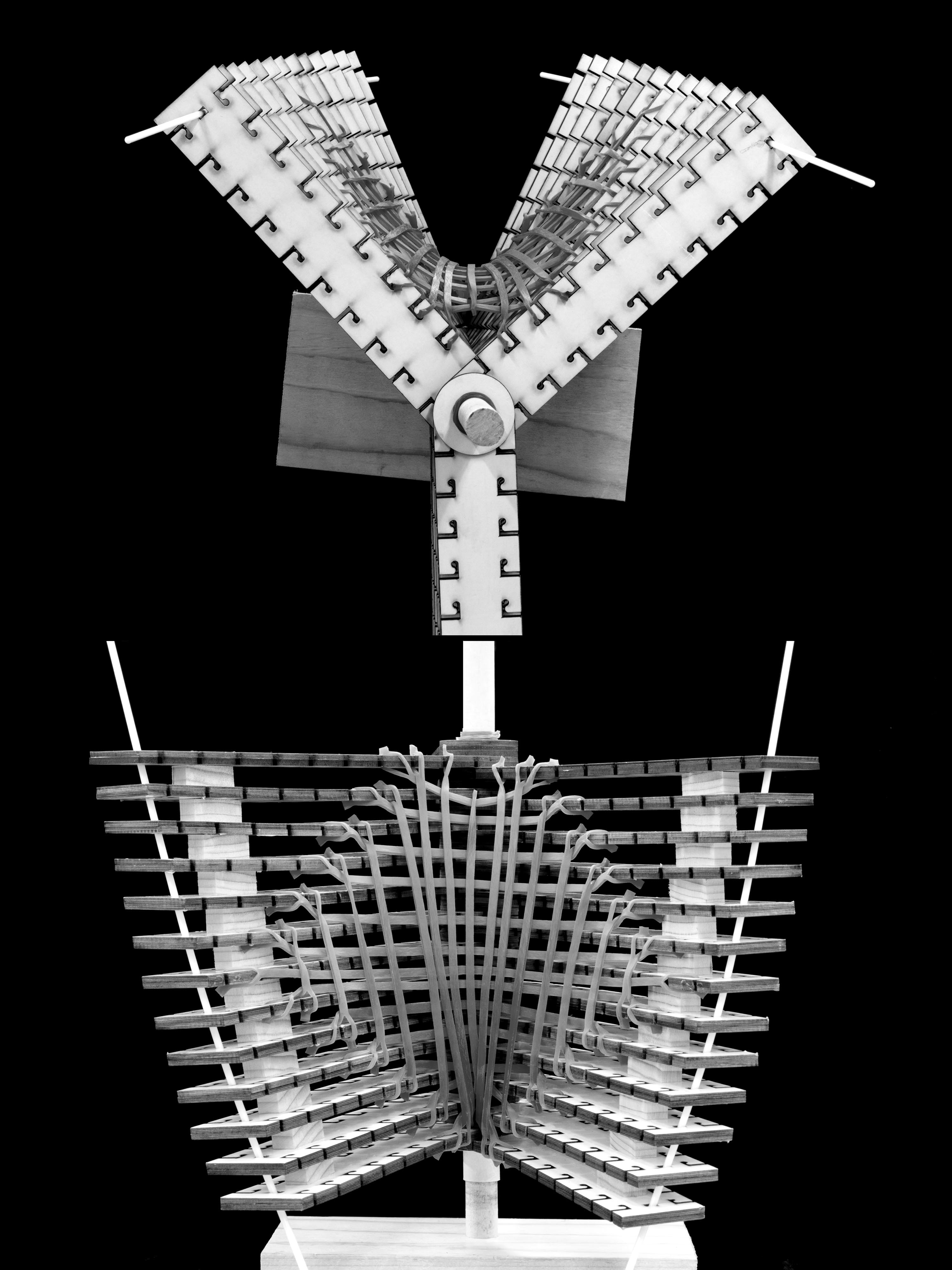
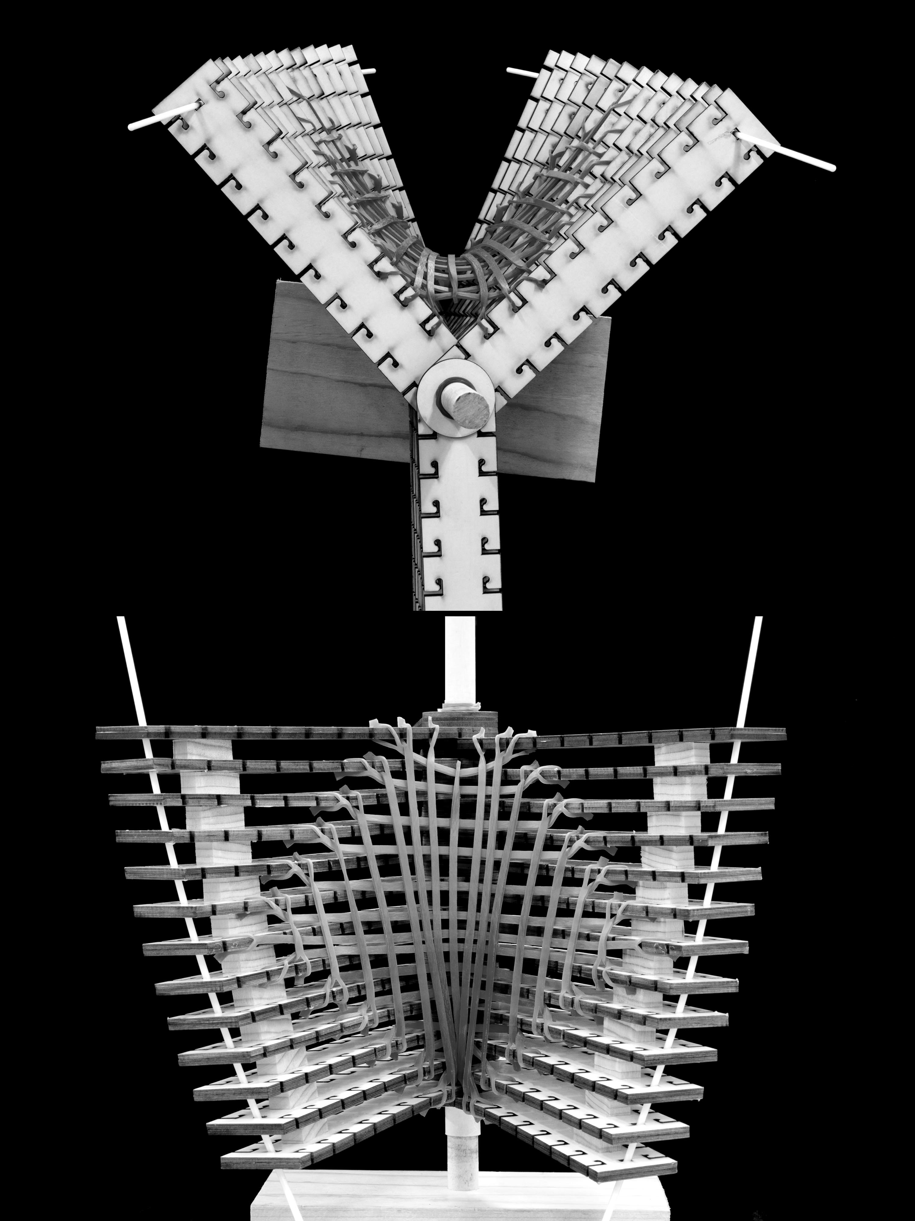
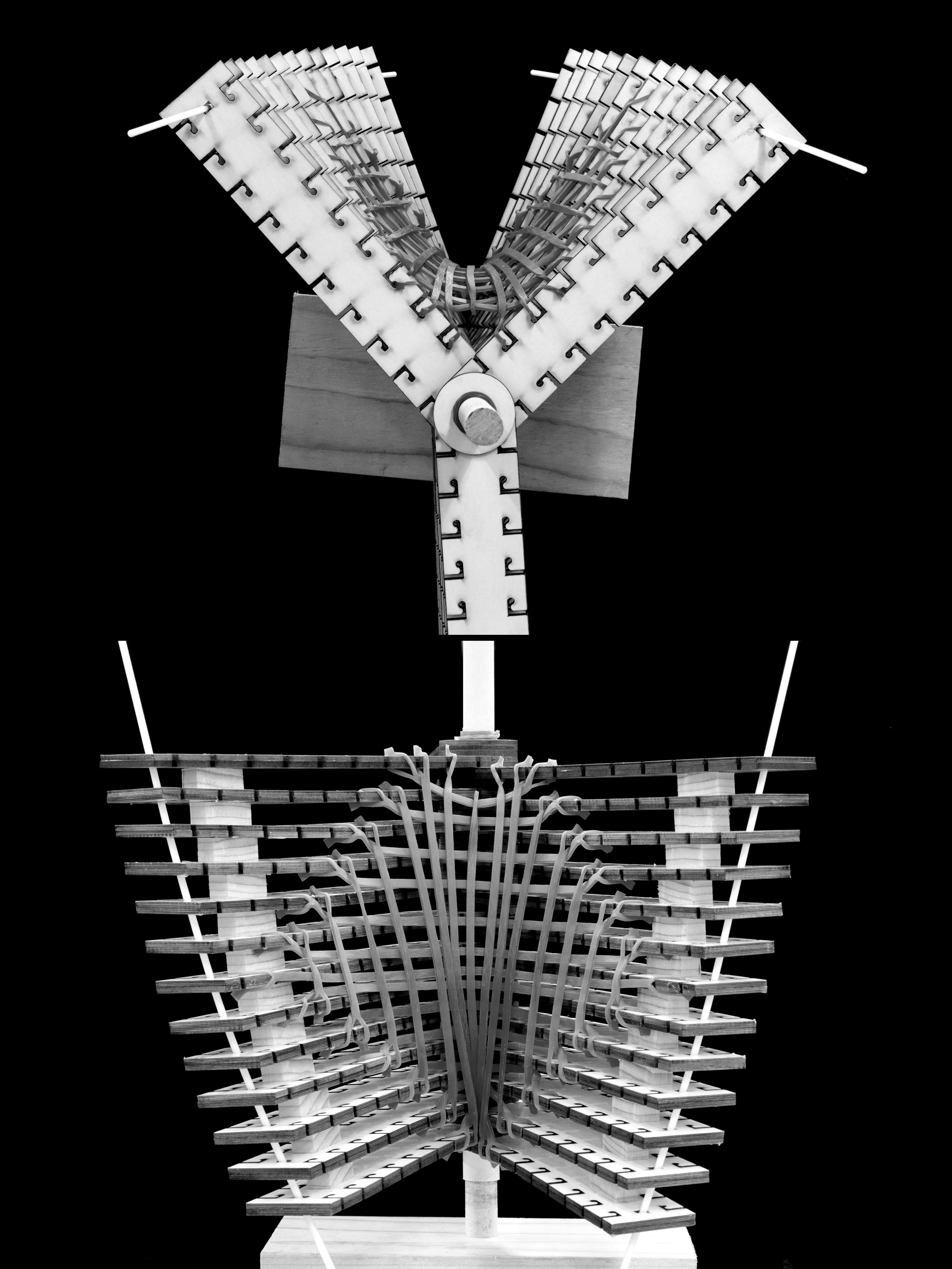
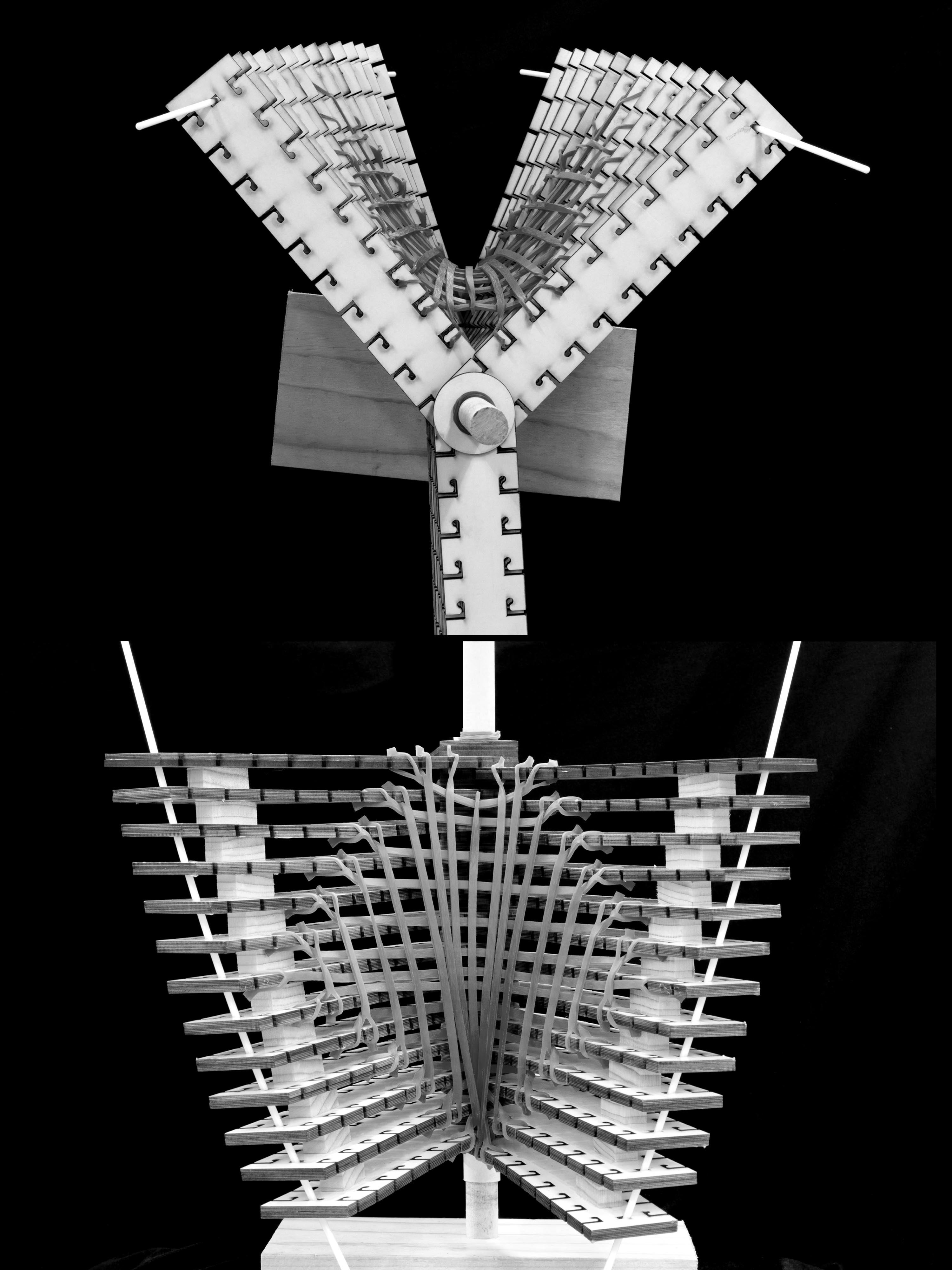
Model Test — Direct Transformation
The first model directly translates the three-lobed dragon fruit stem cross-section into a three-dimensional adaptive prototype. Each Y-shaped rib is reproduced as a modular unit and arrayed in a planar grid; the array rotates collectively around the central axis in response to solar angle, transitioning from a near-closed position that reflects high-angle summer sun to an open position that admits low-angle winter light. The model demonstrates that a direct geometric translation of the biological mechanism is sufficient to produce a functionally responsive shading surface, providing the formal and structural basis for all subsequent iterations.
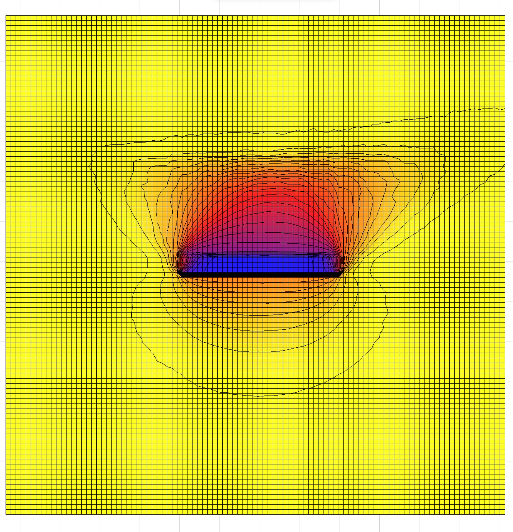
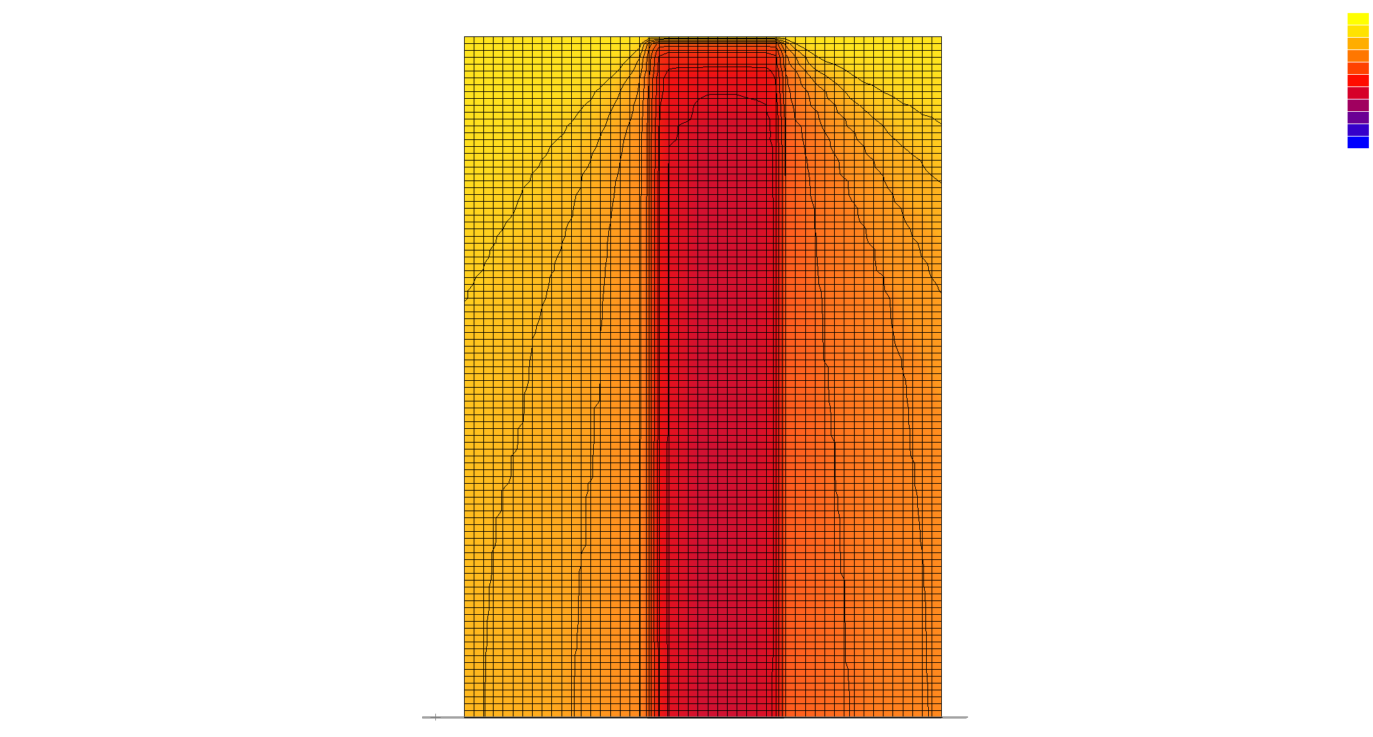
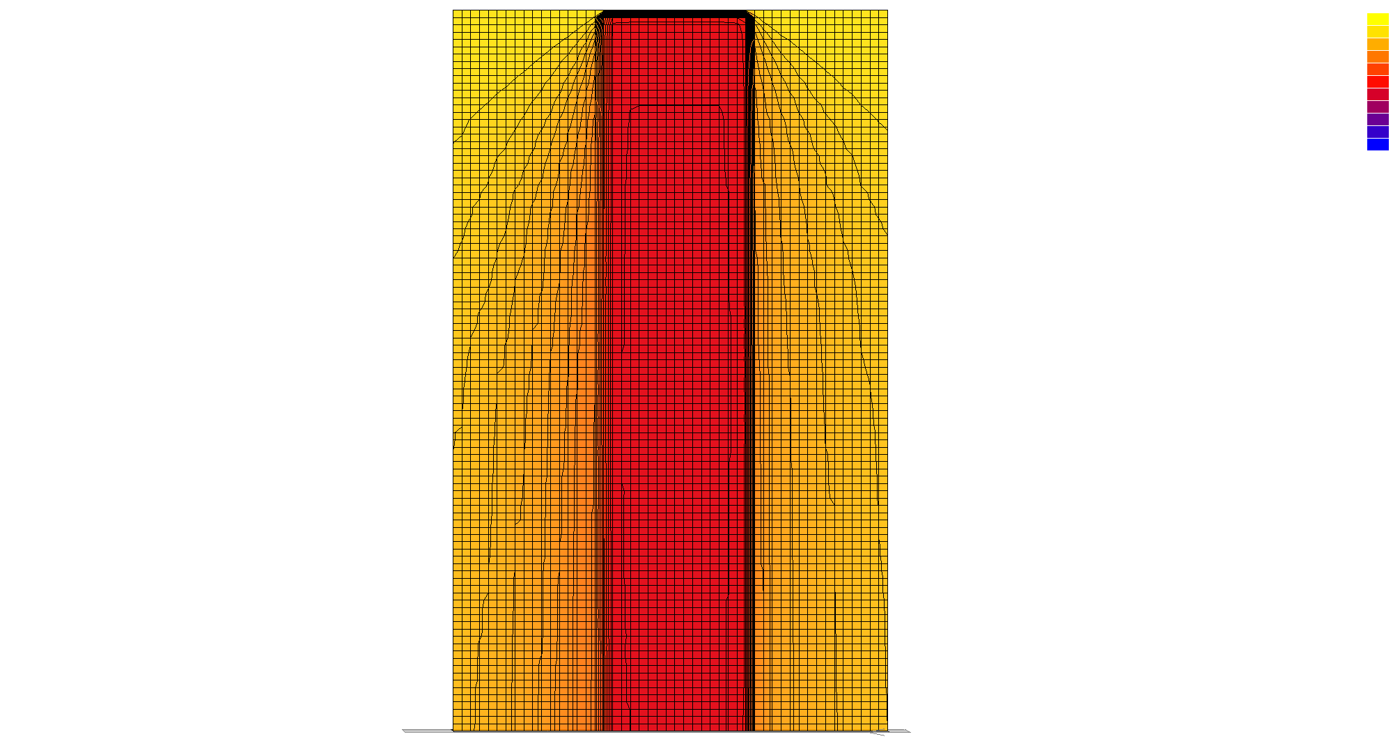
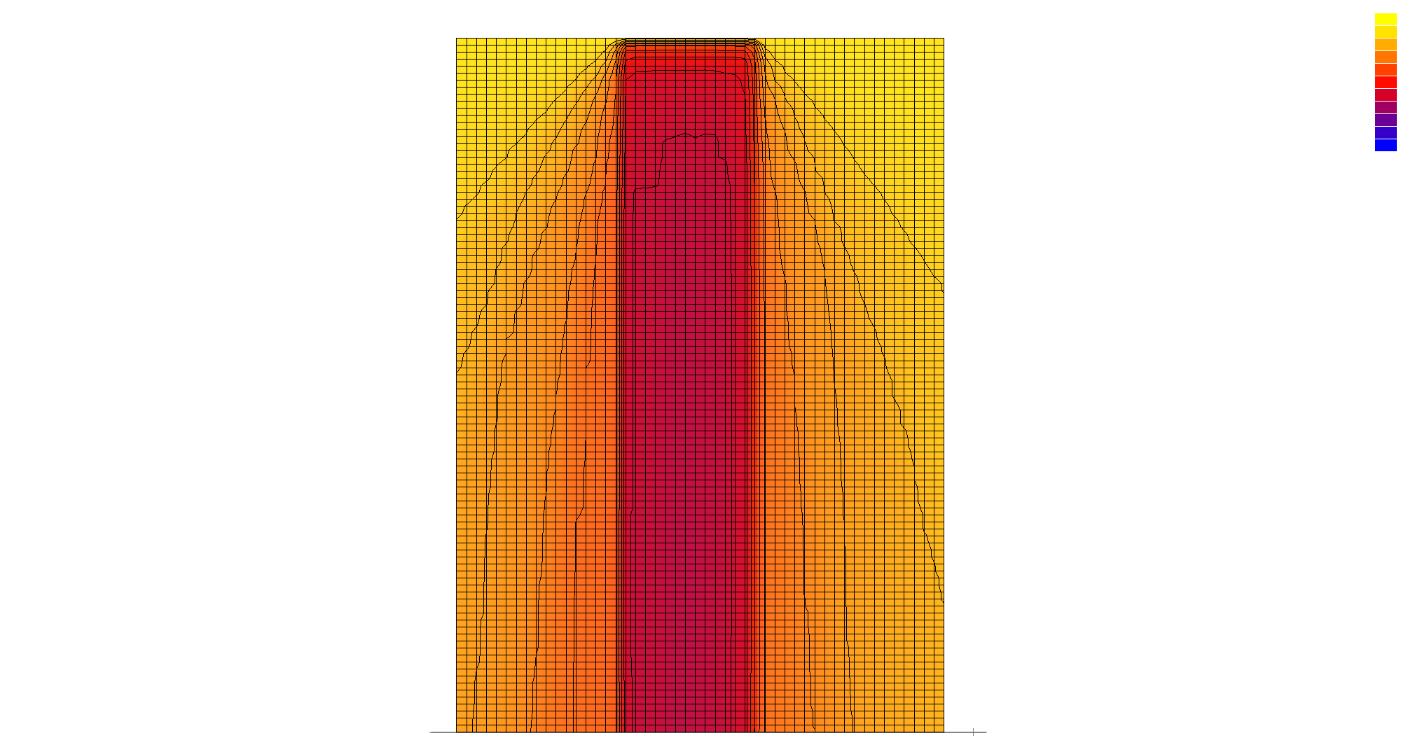
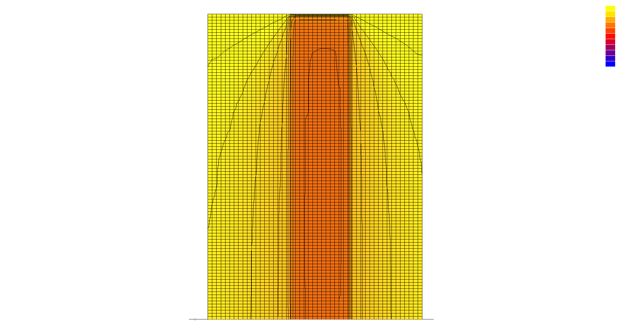
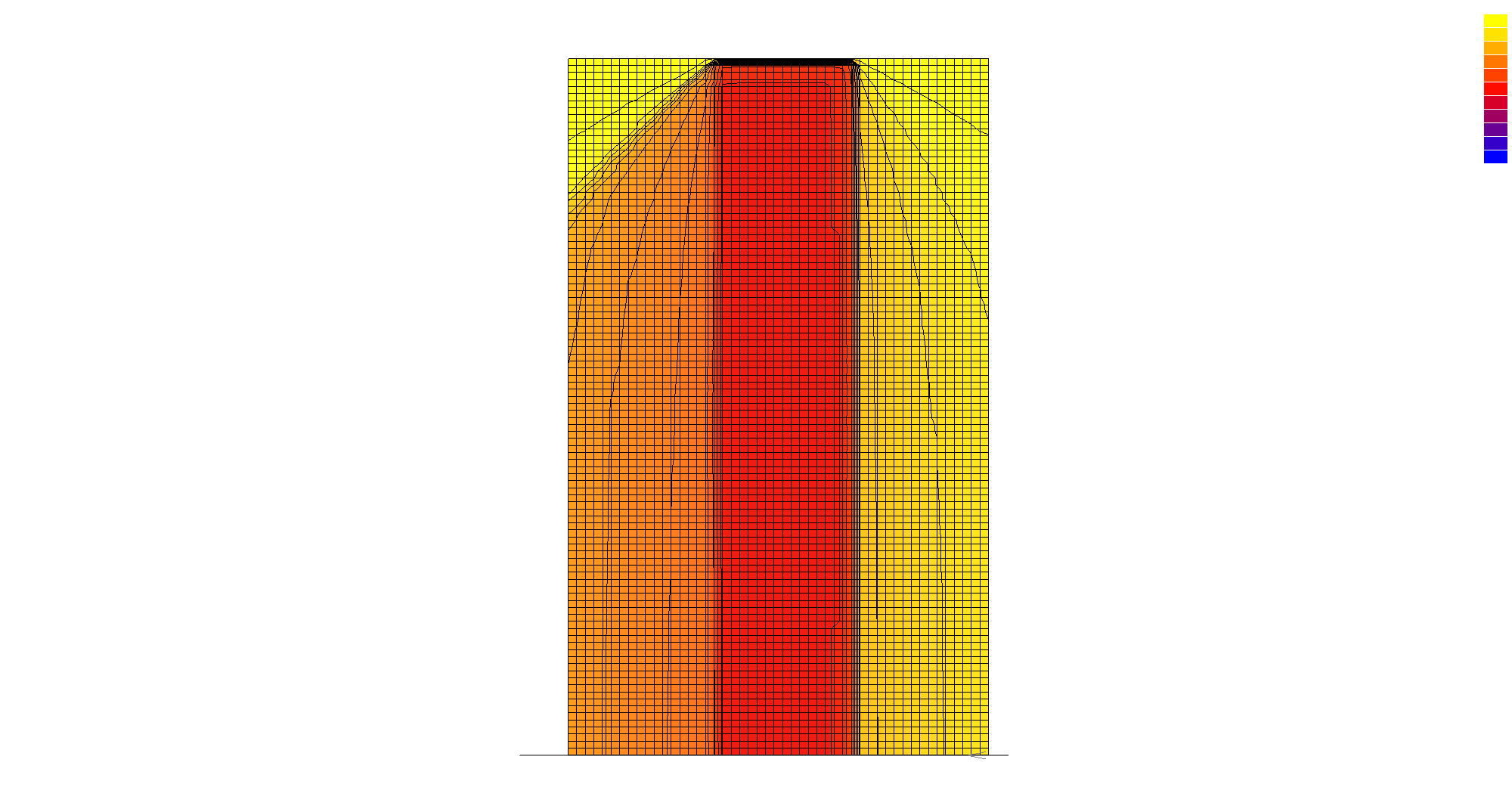
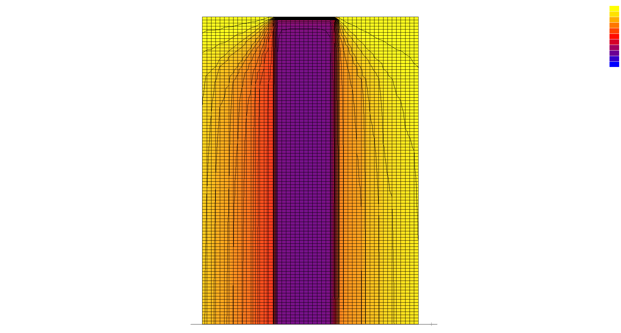
Light Transmission Analysis
Two light transmission modes were examined in relation to the rotation state of each fin unit. In the direct mode, sunlight passes through the apertures as concentrated beams, producing sharp shadow bands on the interior surface. In the diffuse mode, the angled fins scatter incoming light, redistributing it evenly across the receiving plane. The ratio of direct to diffuse transmission is continuously variable through fin rotation, giving the surface a tunable response to changing solar conditions.
Direct light transmission
Diffuse light transmission
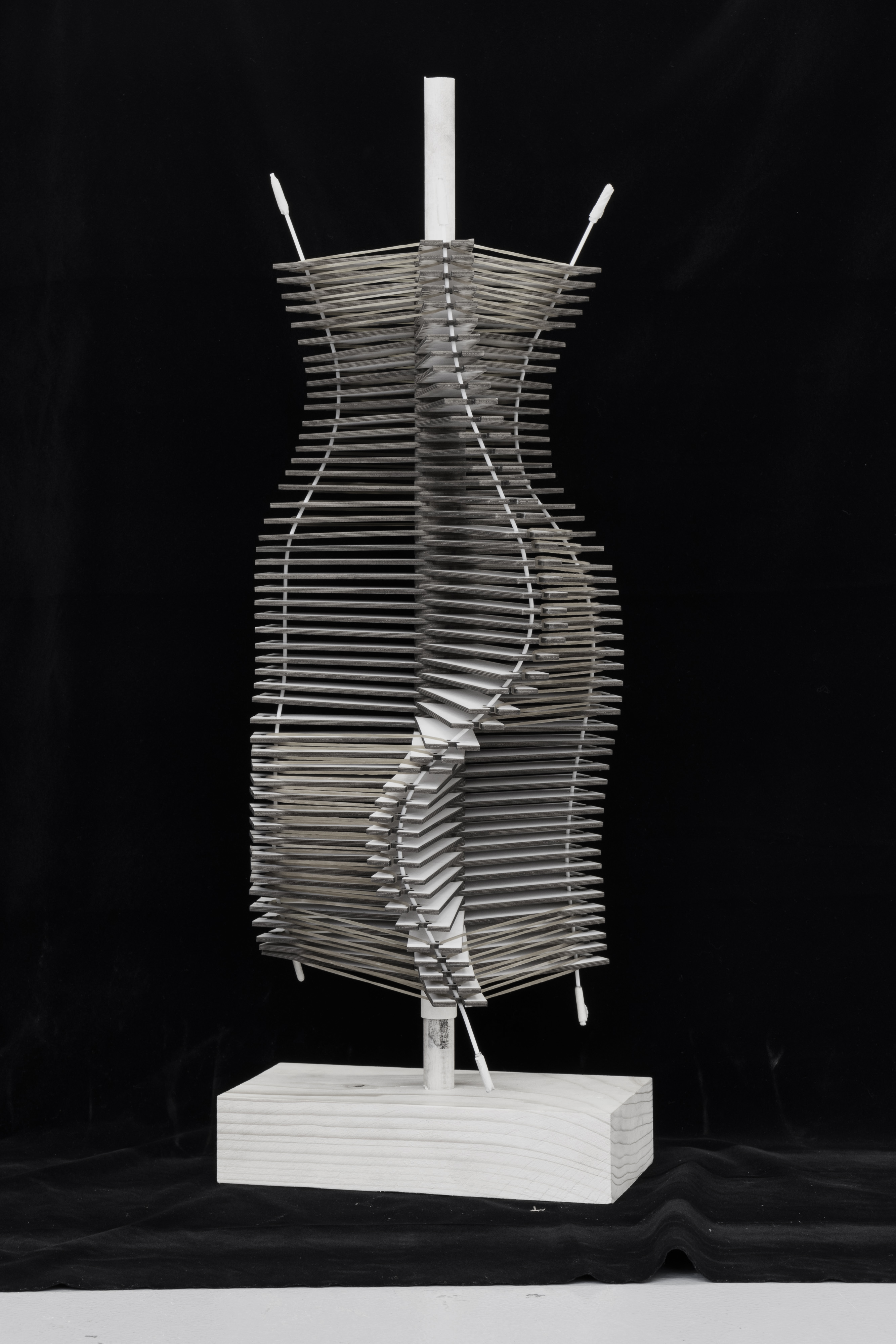
Single Surface Transformation
The second model refines the adaptive prototype into a single-layer surface: a planar array of parallel fins that each rotate independently around a shared axis. Compared to the first model, the single surface system reduces material complexity while preserving the core adaptive behavior. The 28-state transformation sequence below documents the full range of fin rotation, from maximum closure through to full aperture. Two camera angles record each state, the front view captures the aperture pattern and shadow quality, while the alternate view records the projection depth and structural profile. Together, the 56 images constitute a complete behavioral record of the single surface transformation.
Iteration 1
Iteration 2
Iteration 3
Transformation Sequence — View A
Transformation Sequence — View B
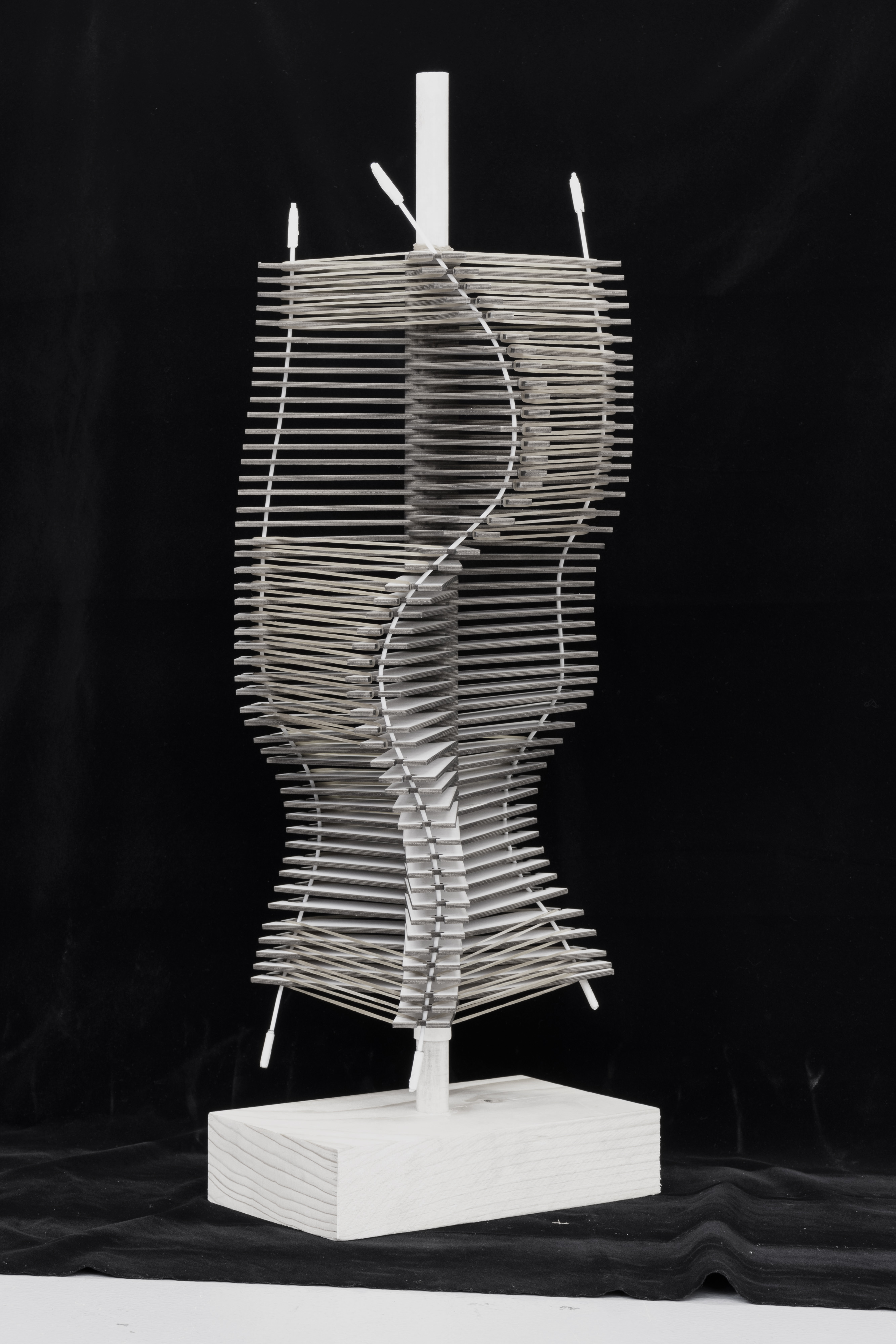
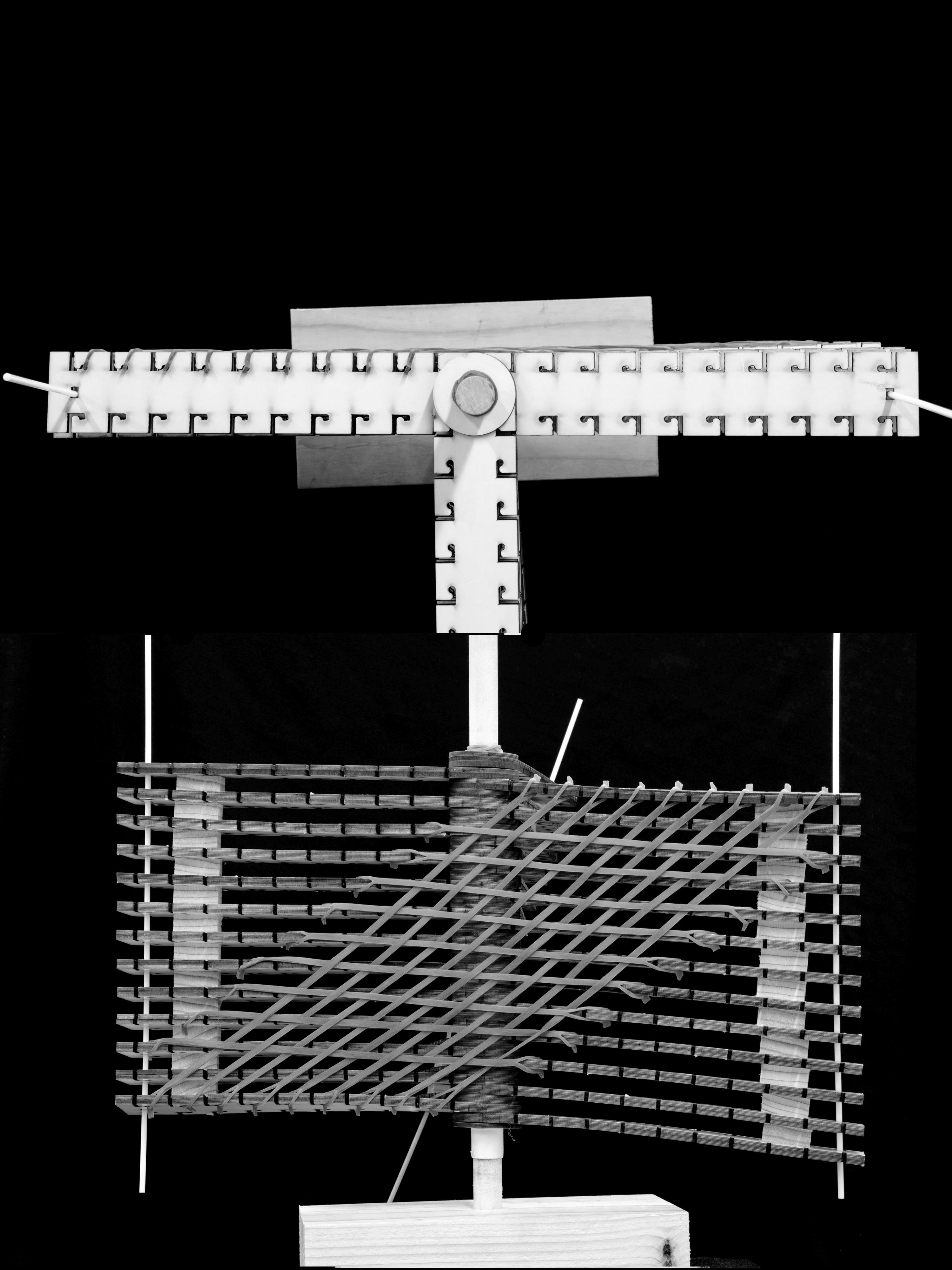
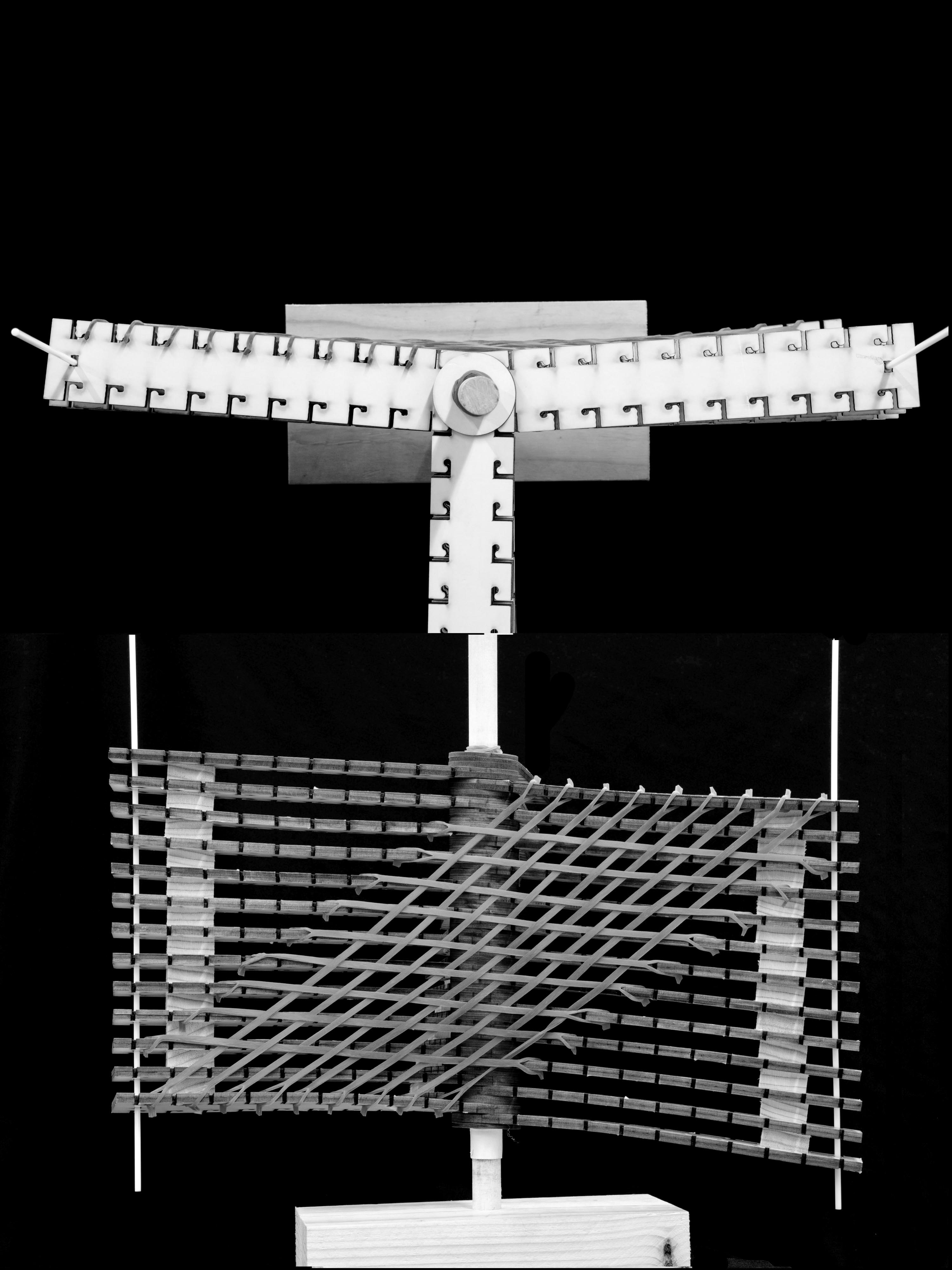
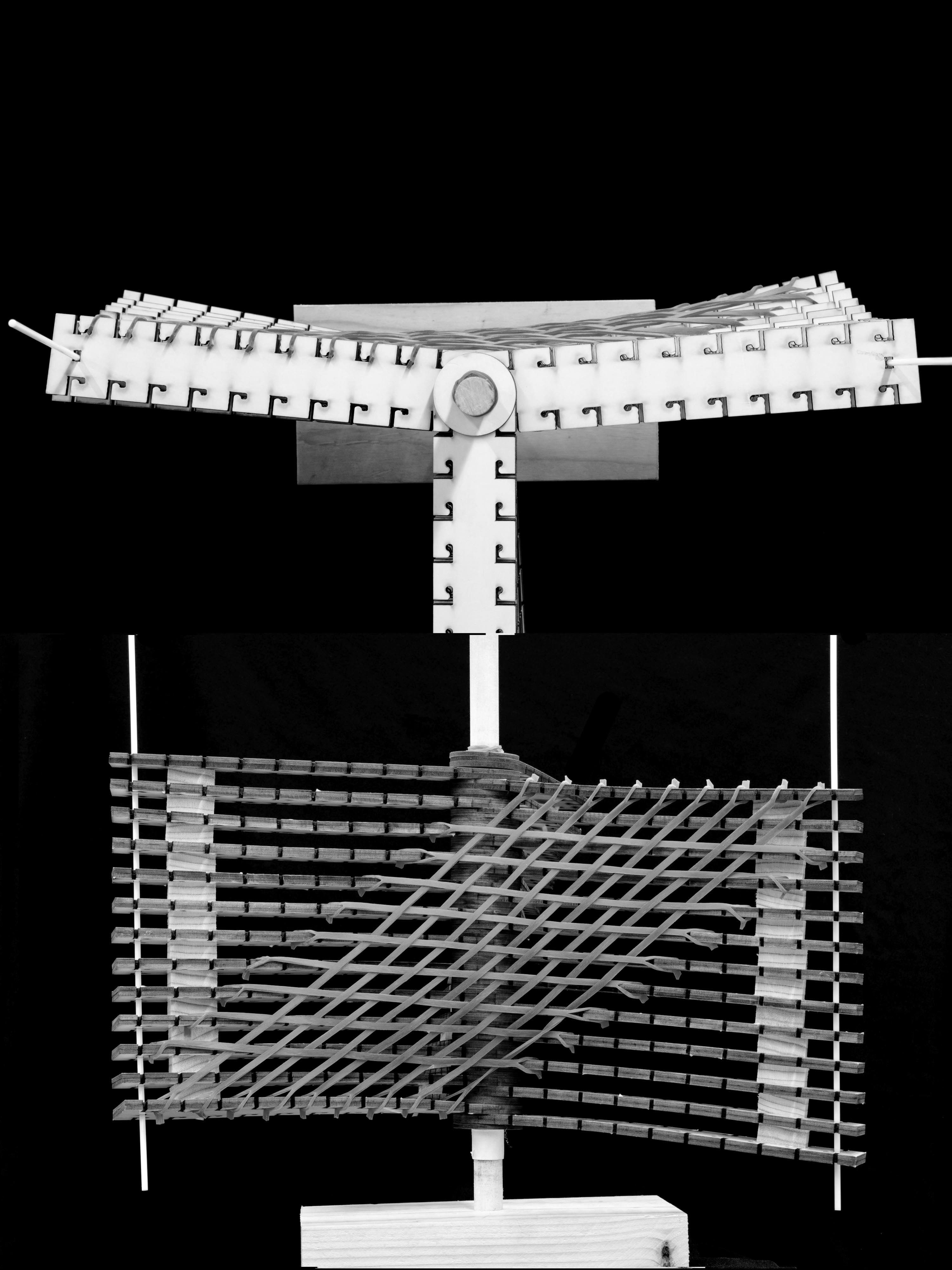
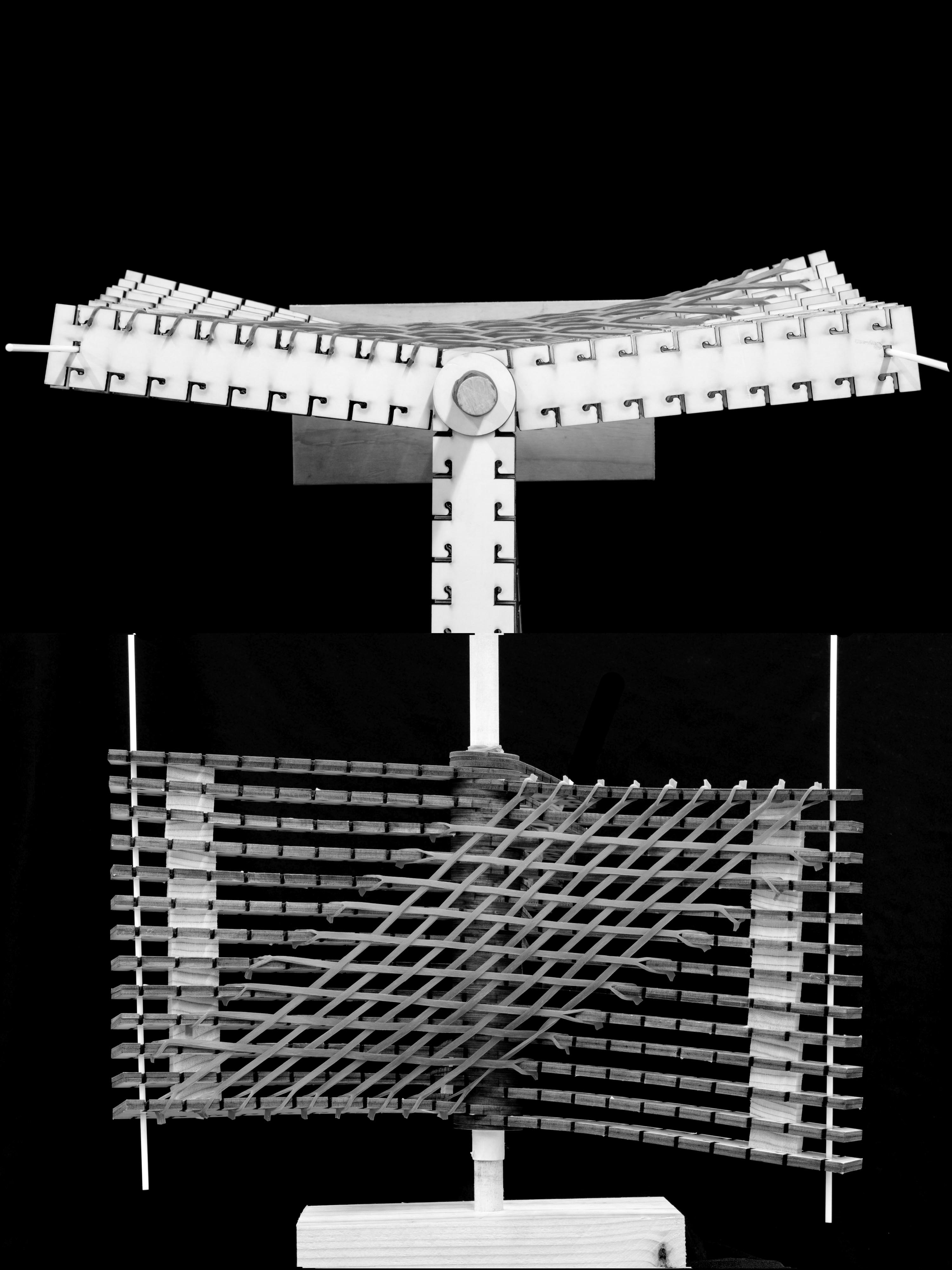
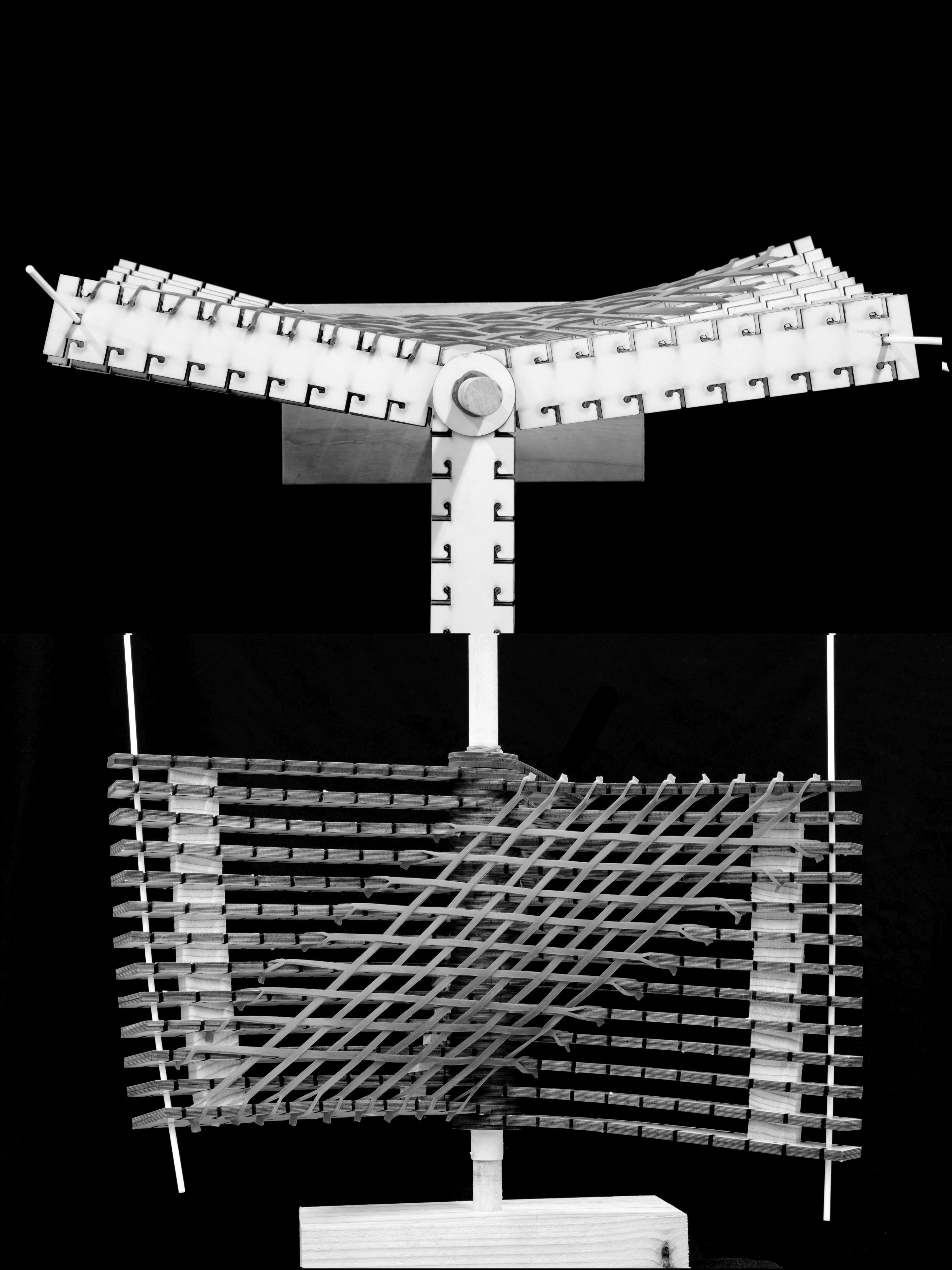
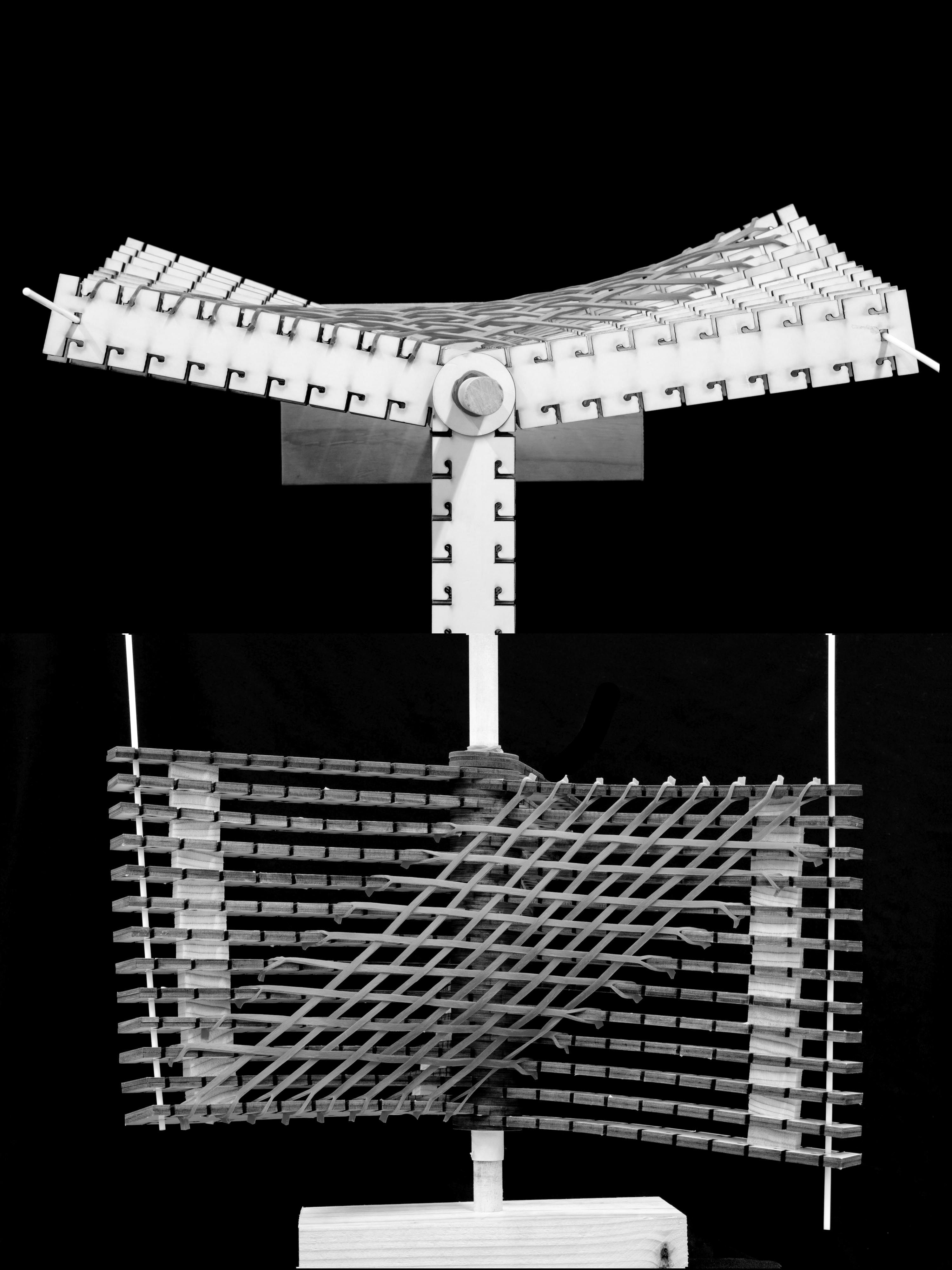
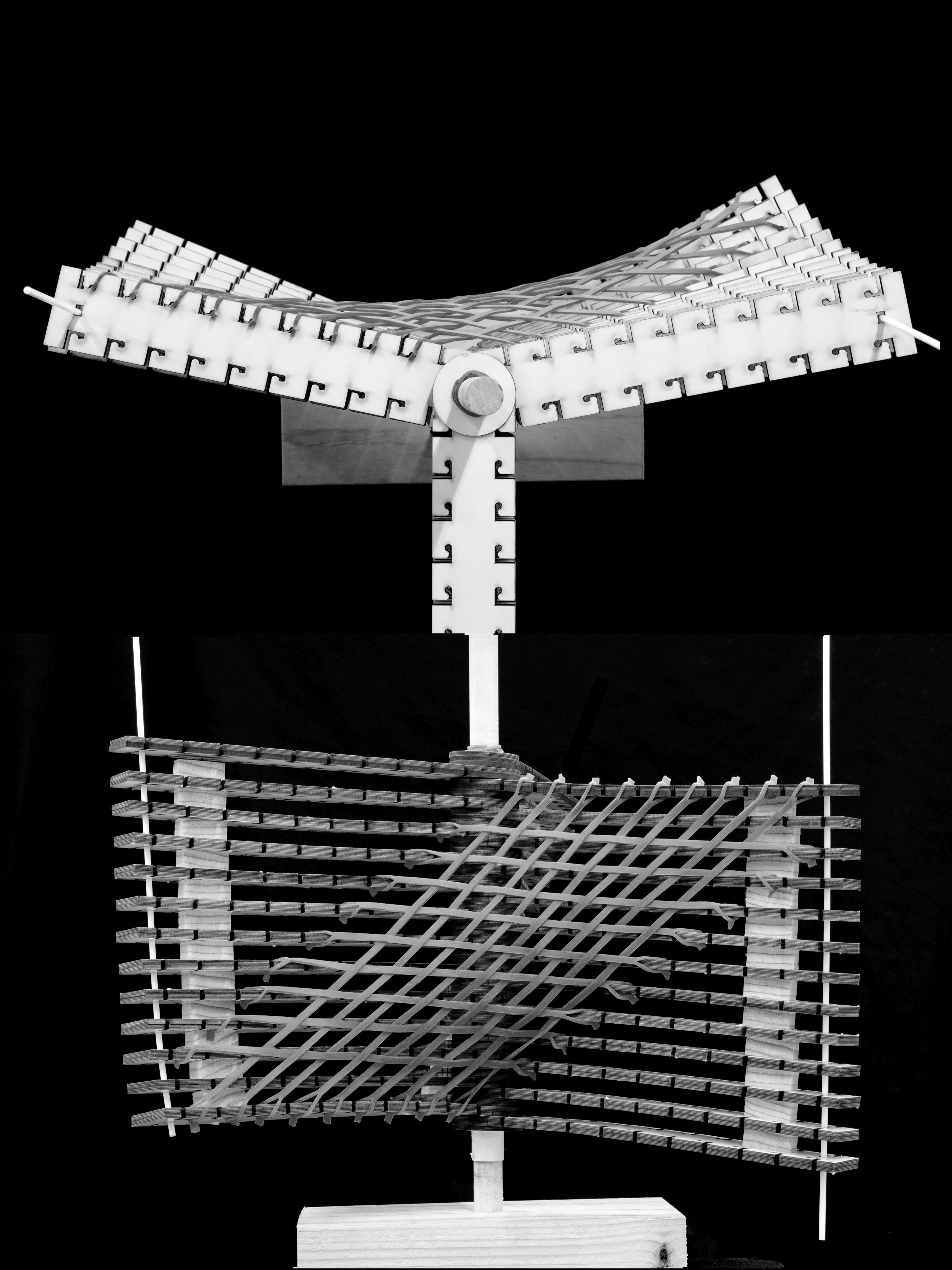
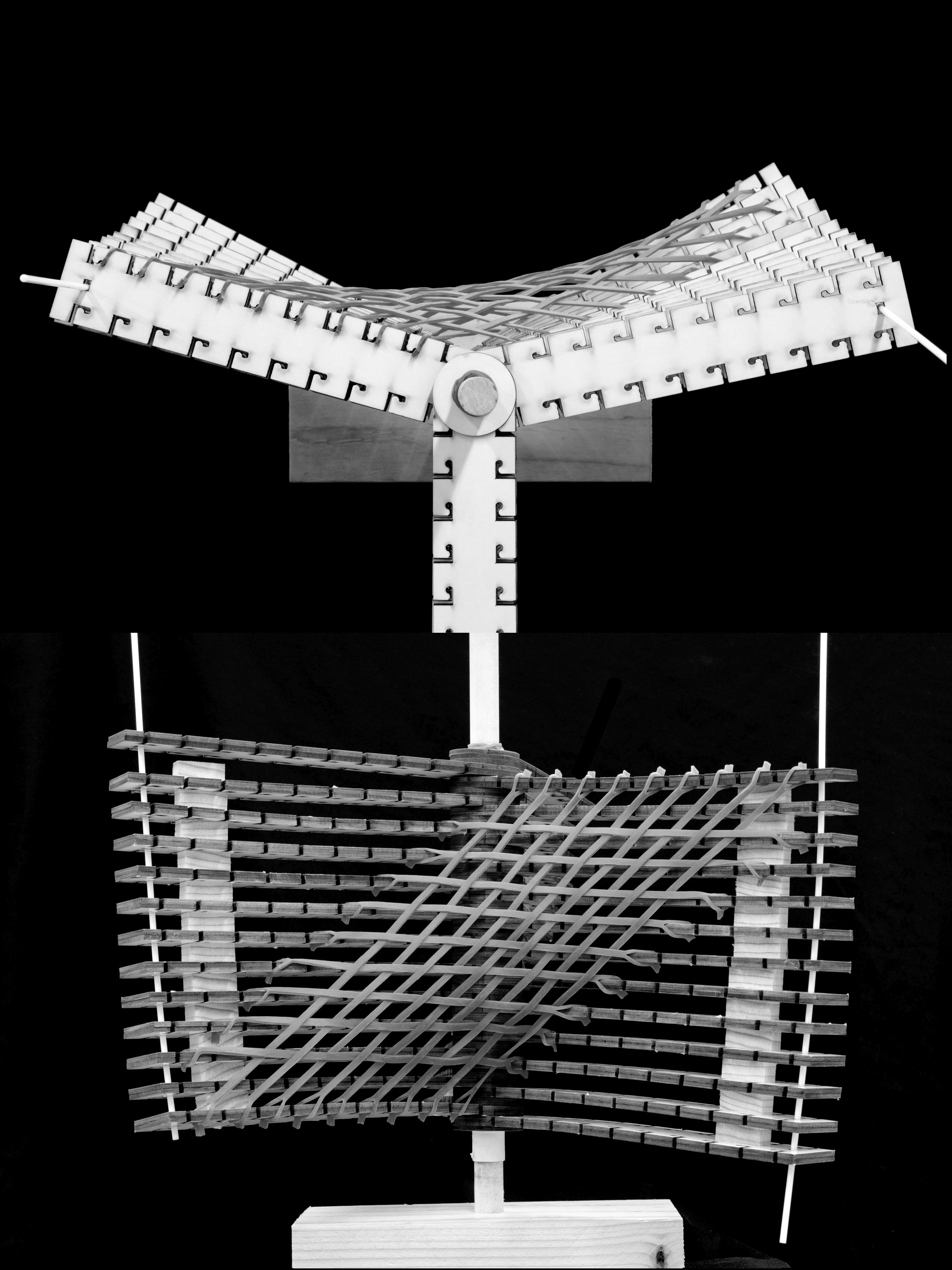
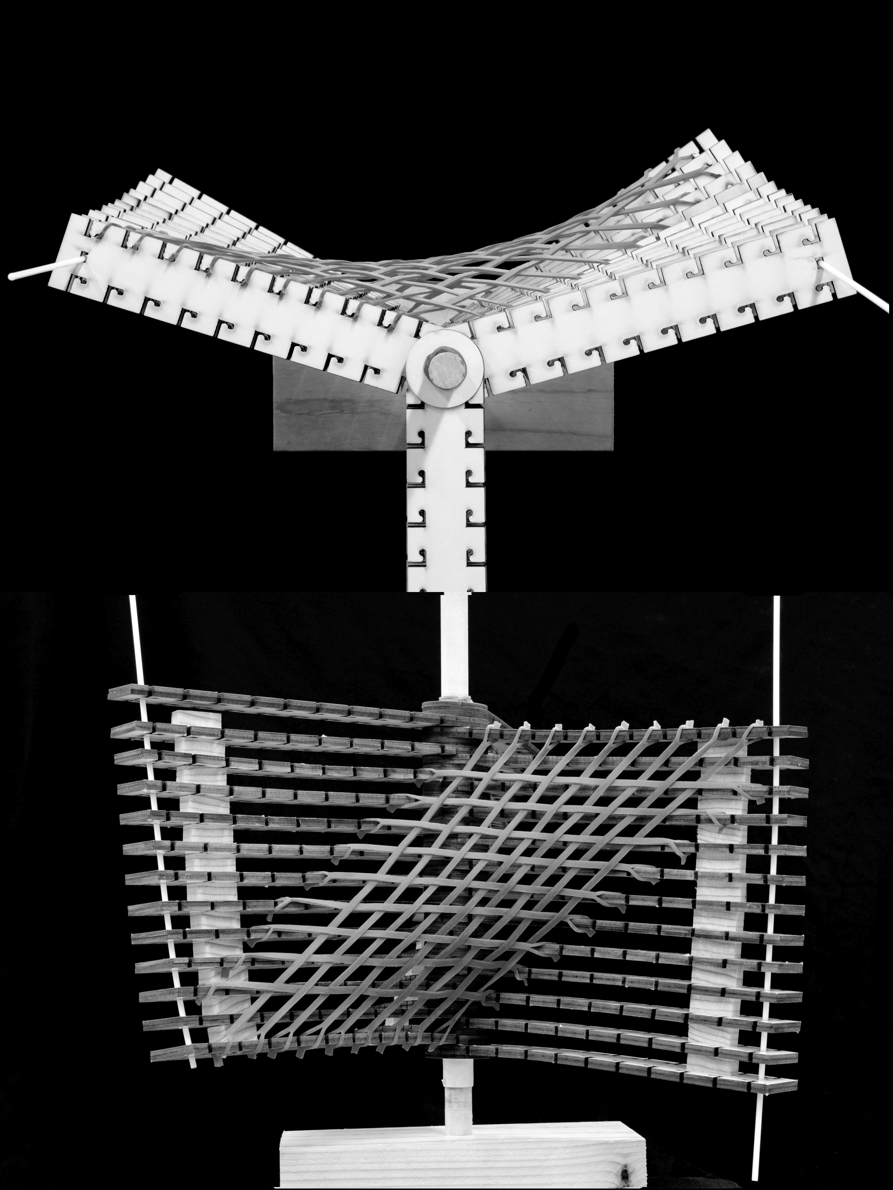
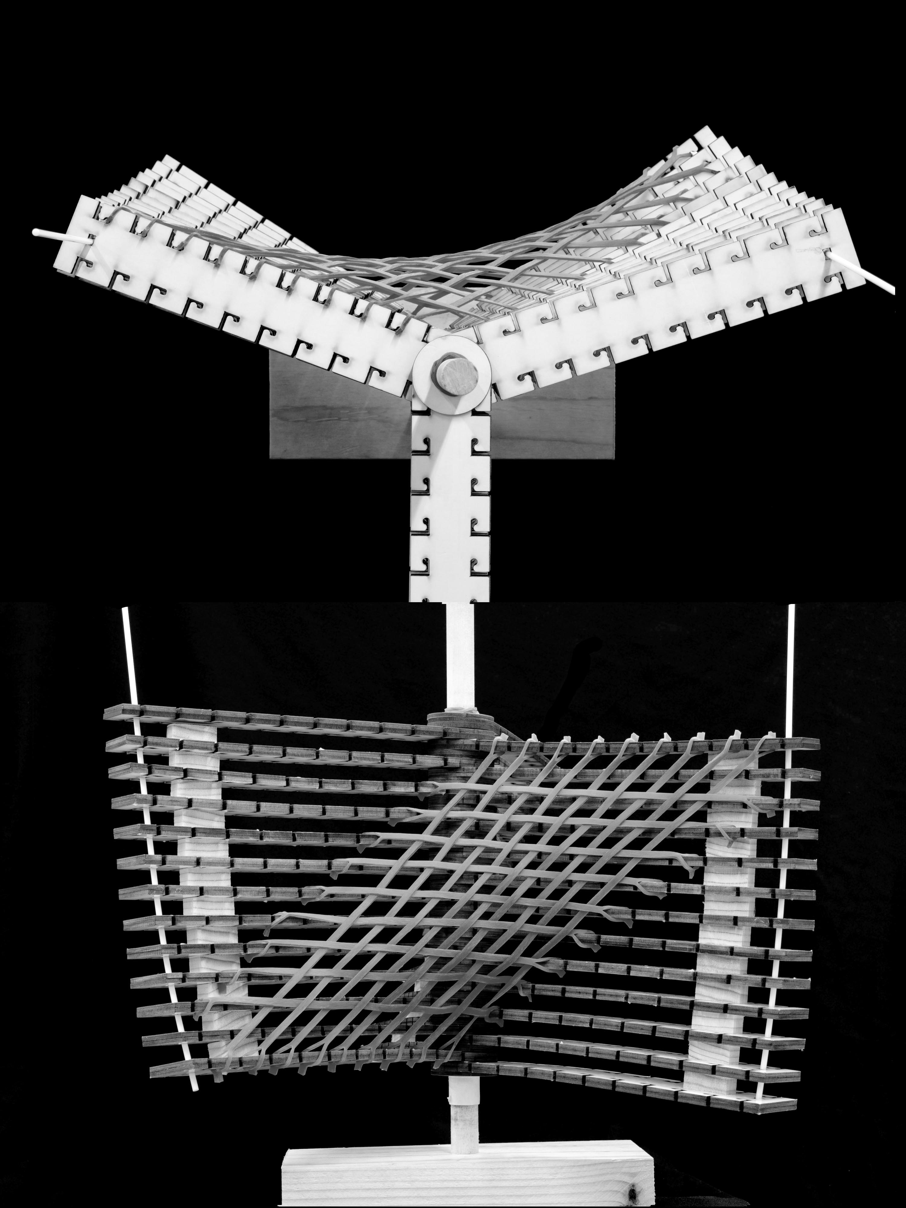
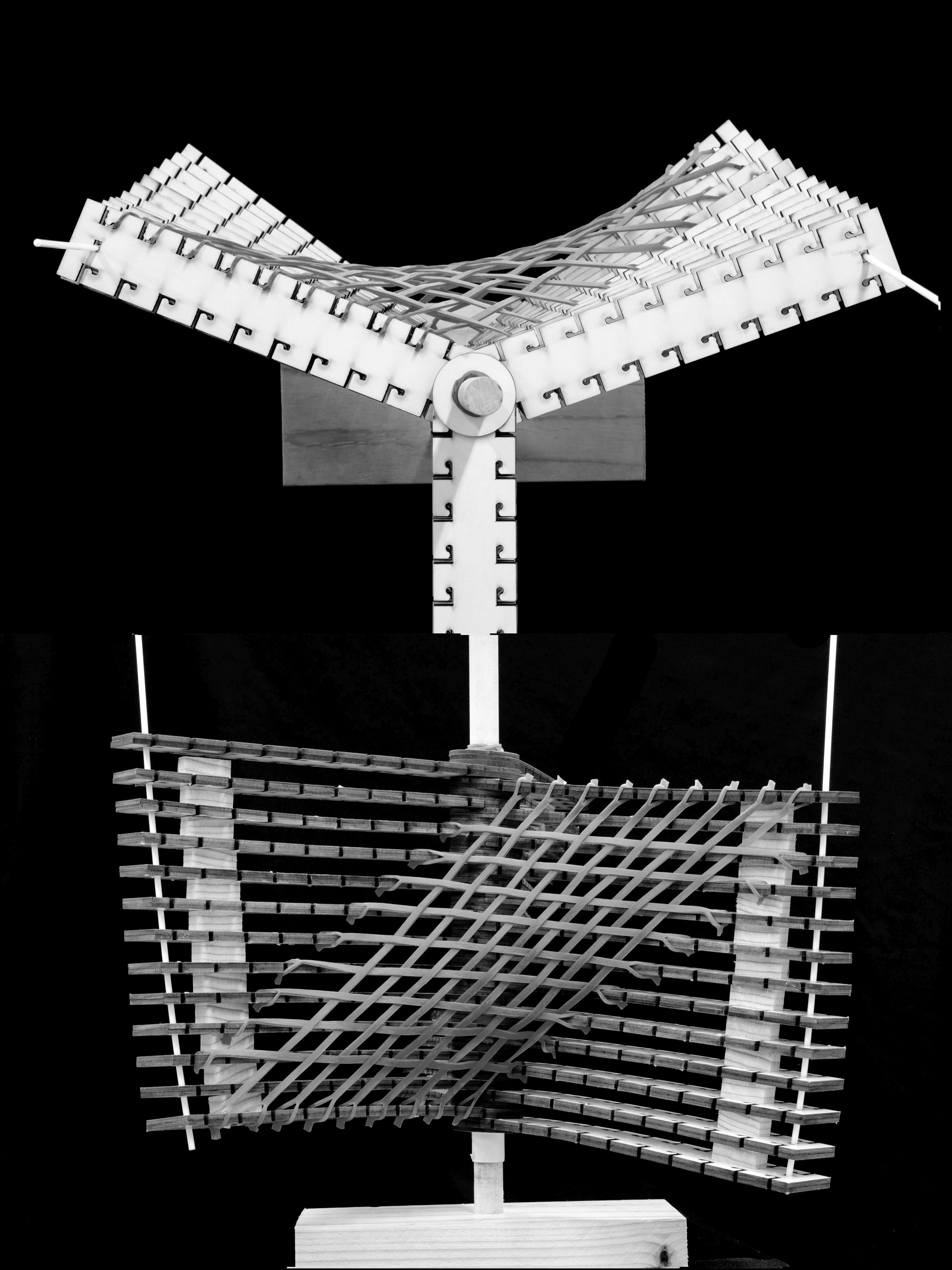
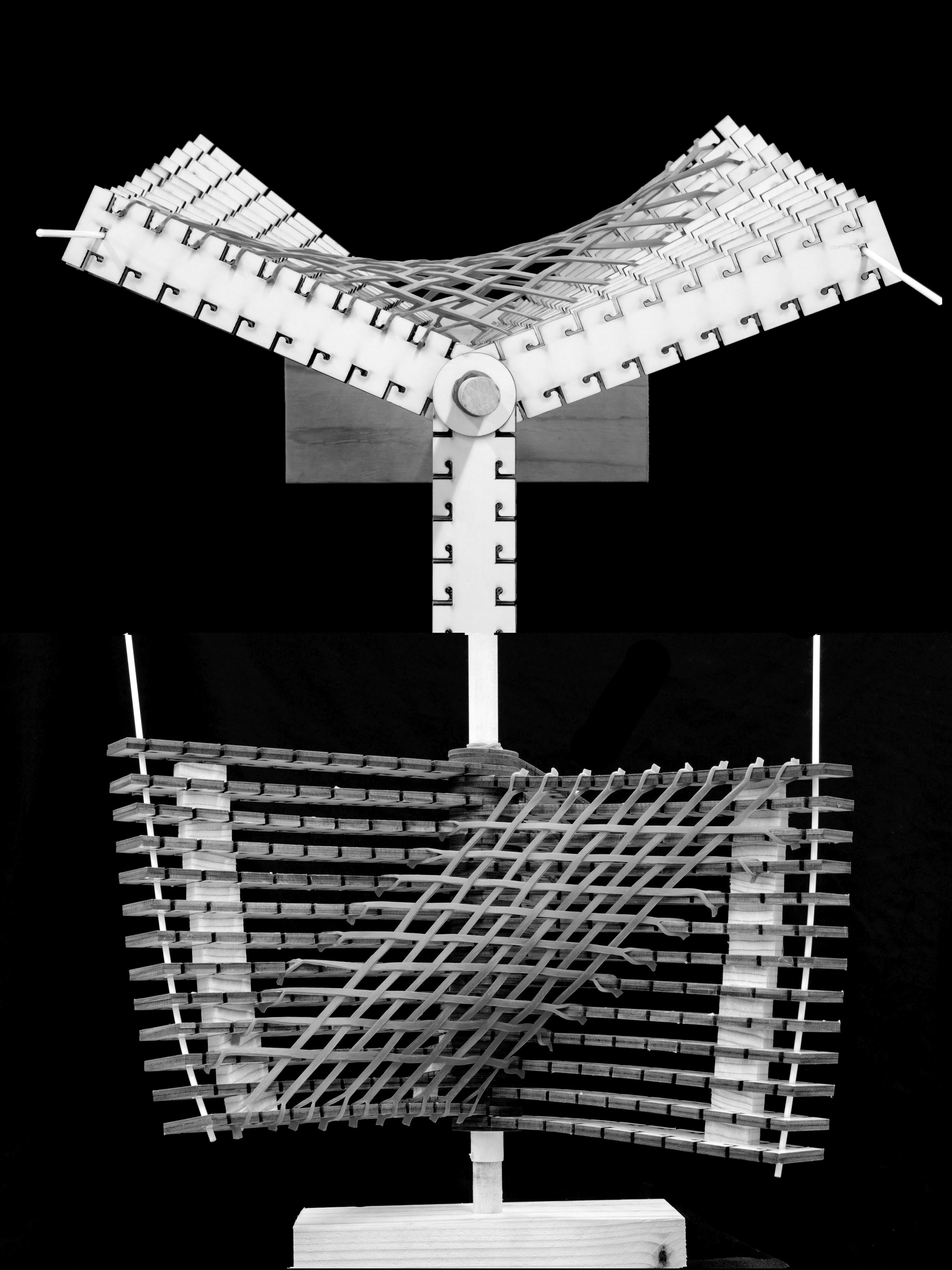
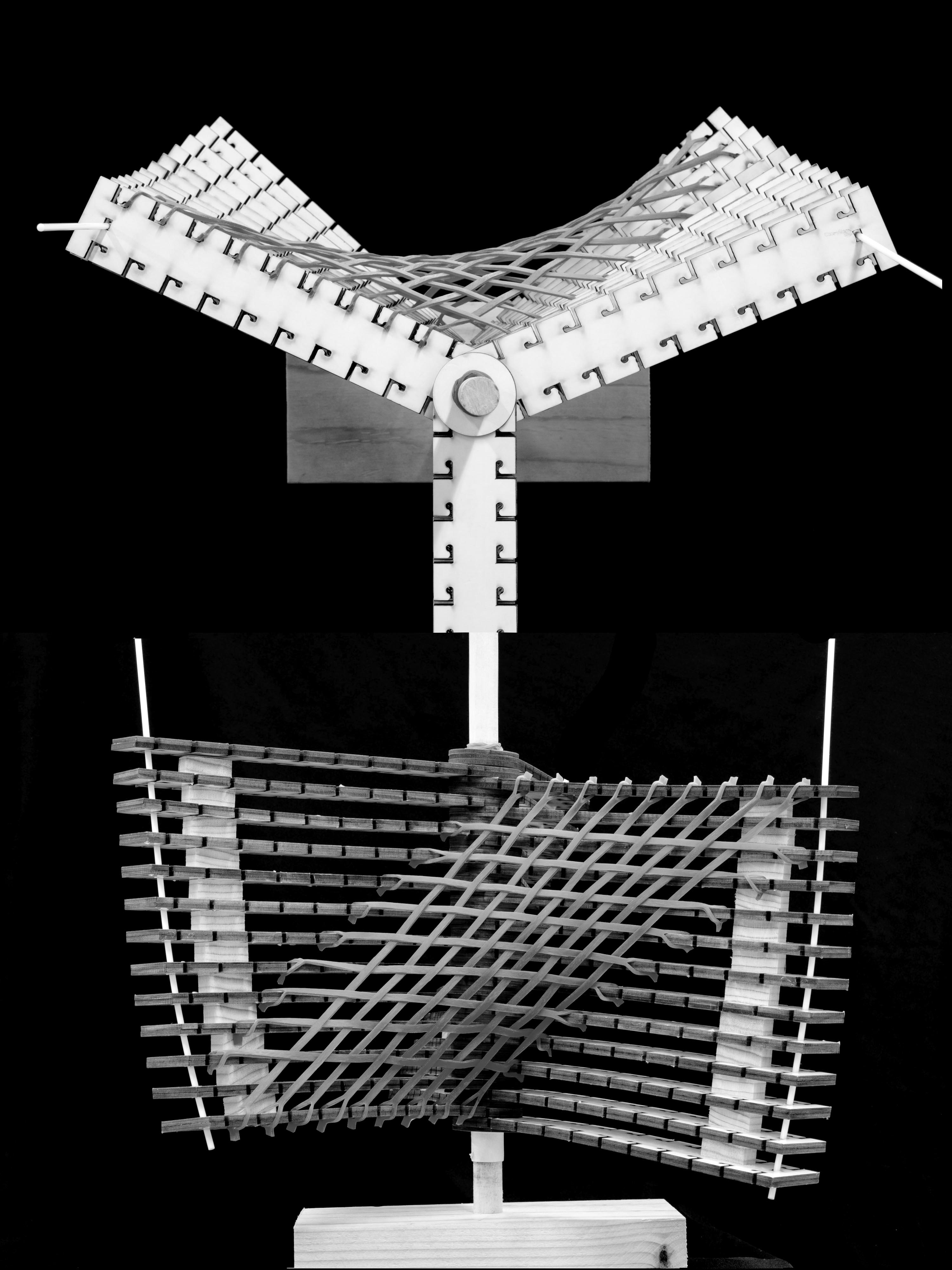
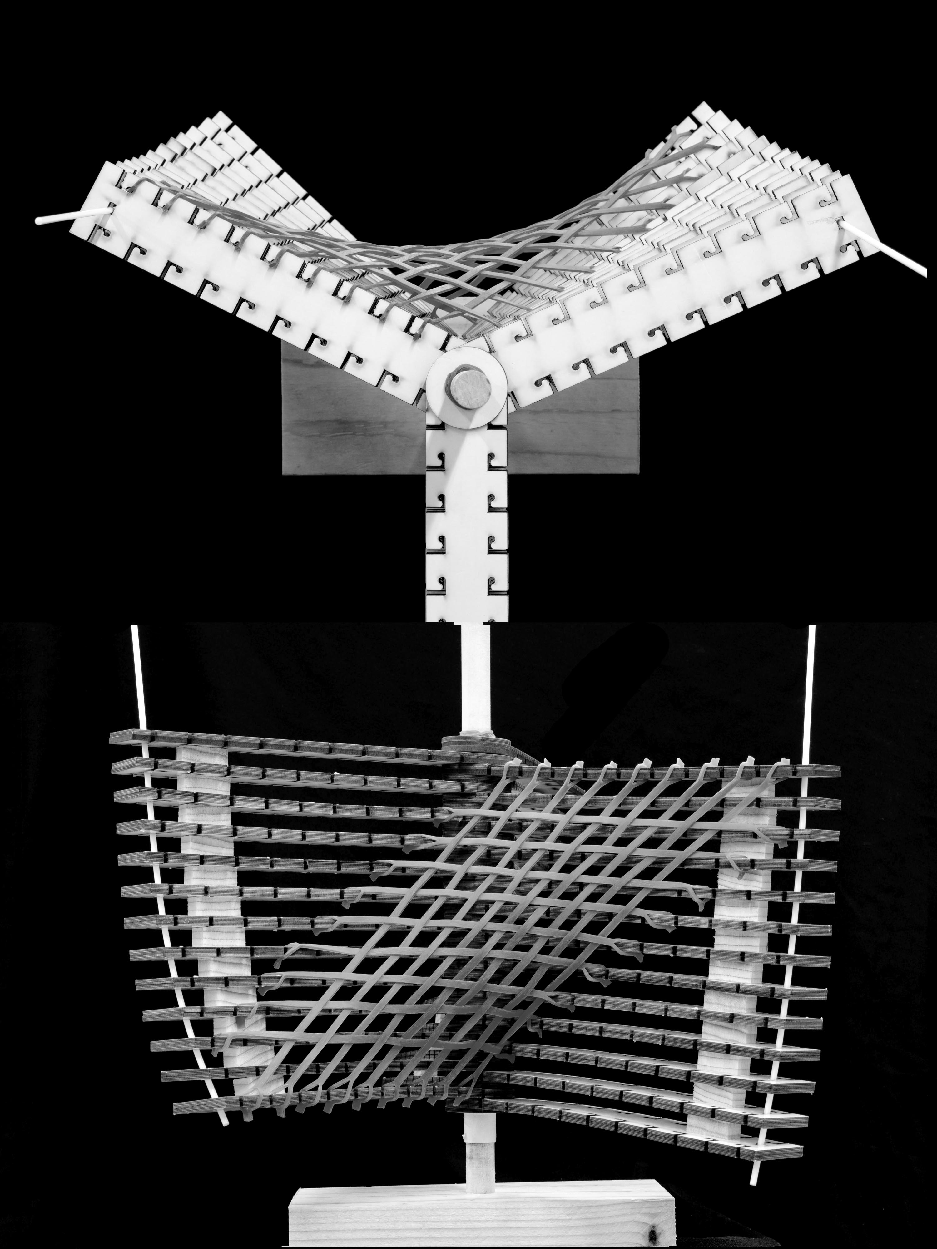
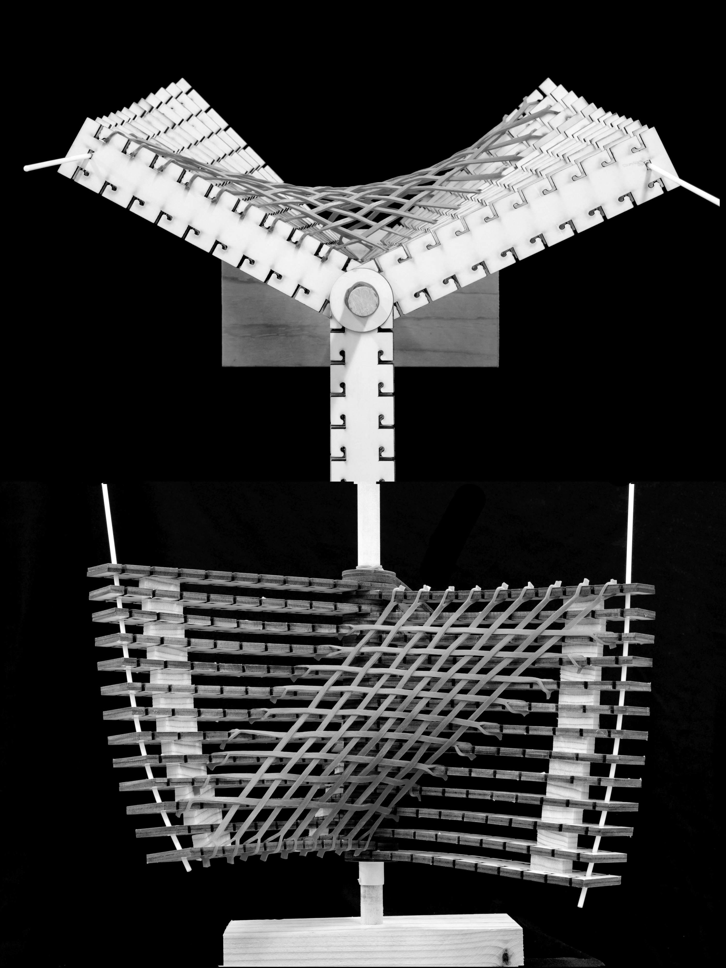
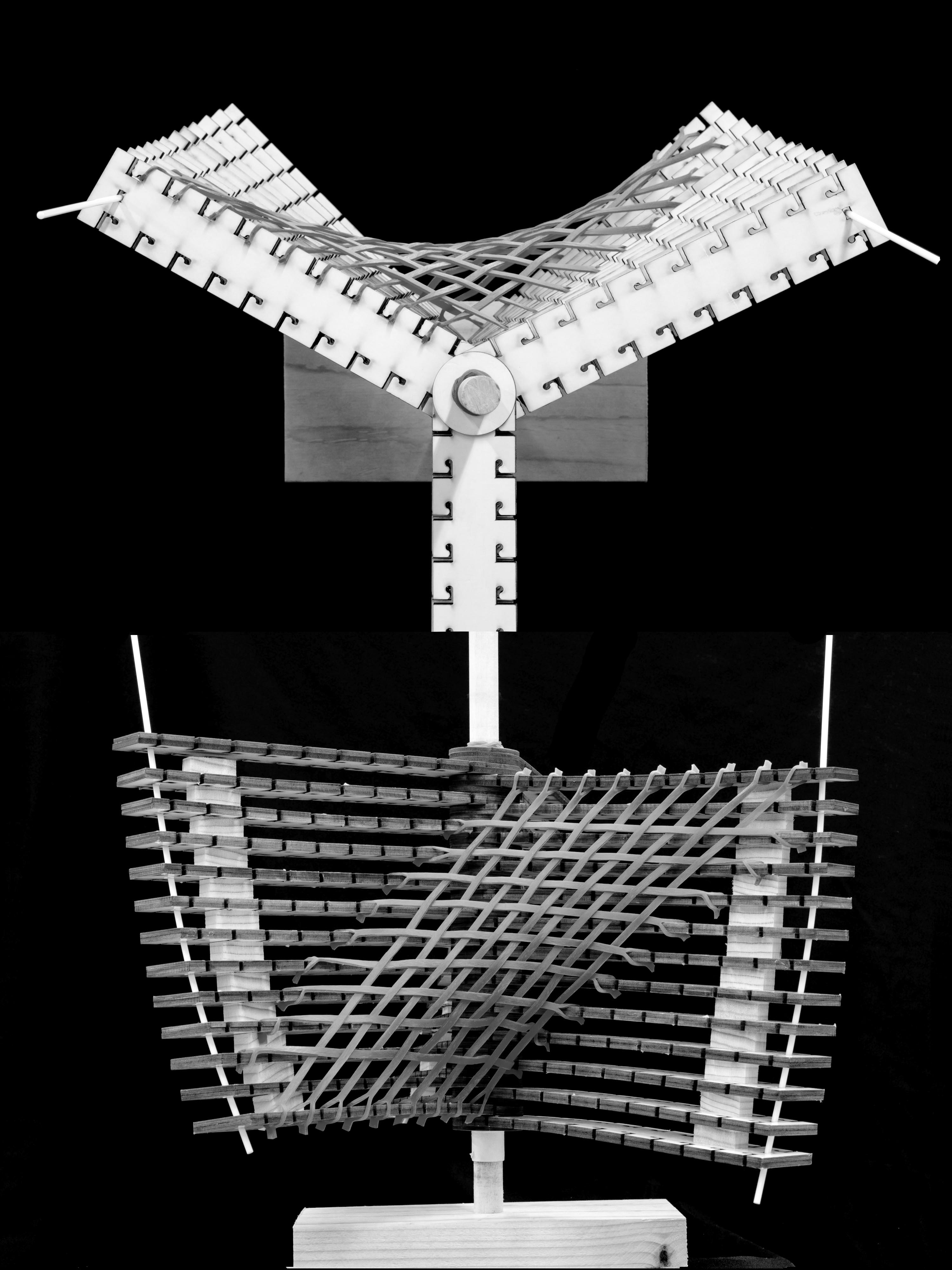
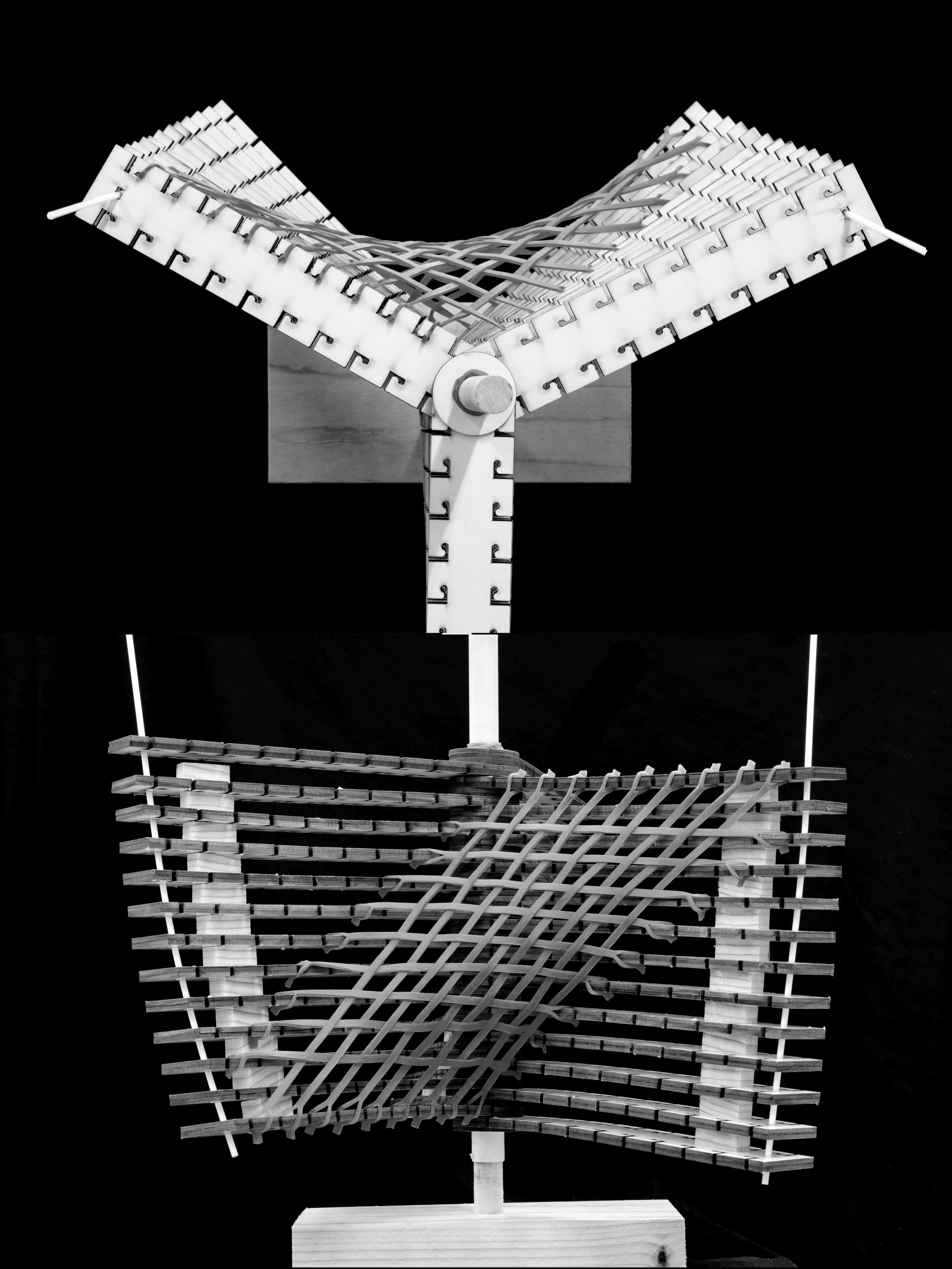
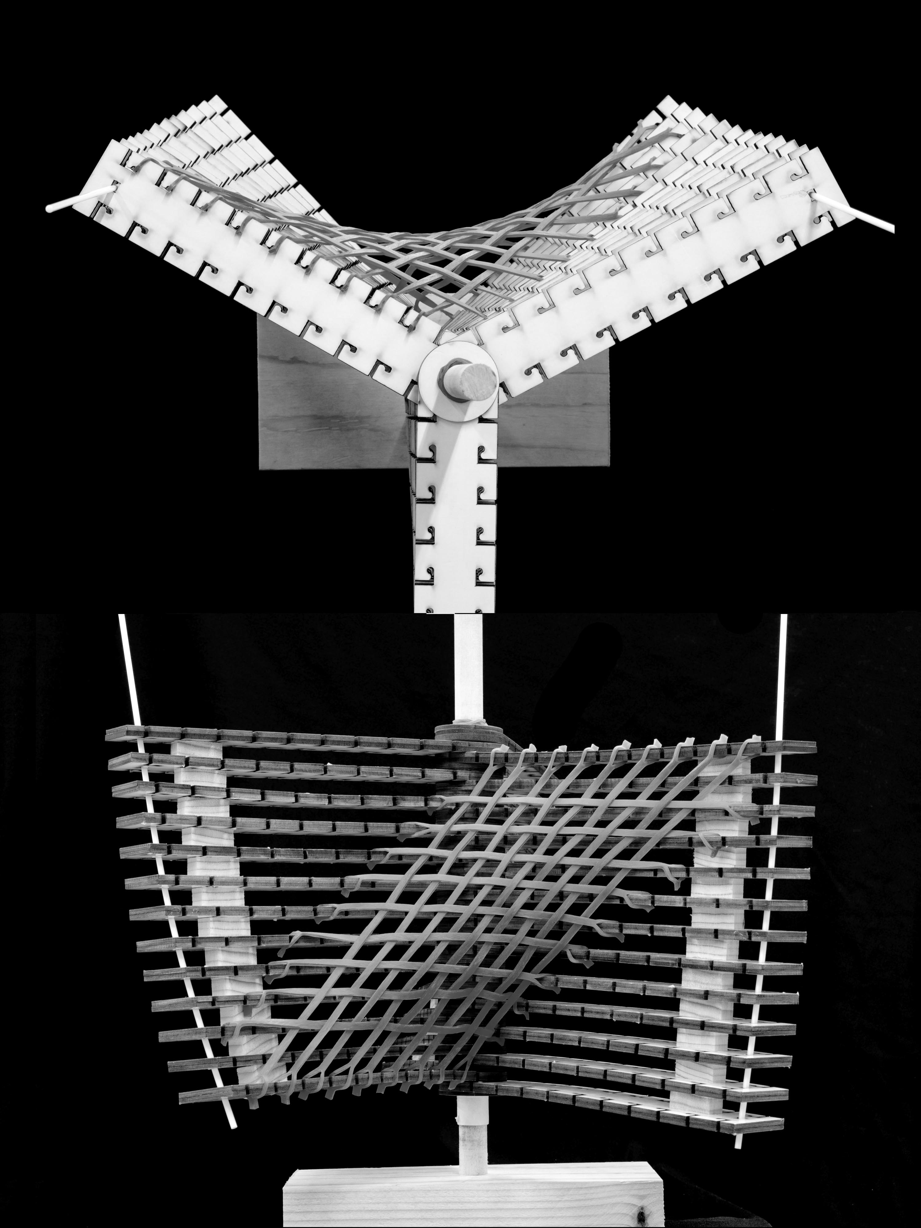
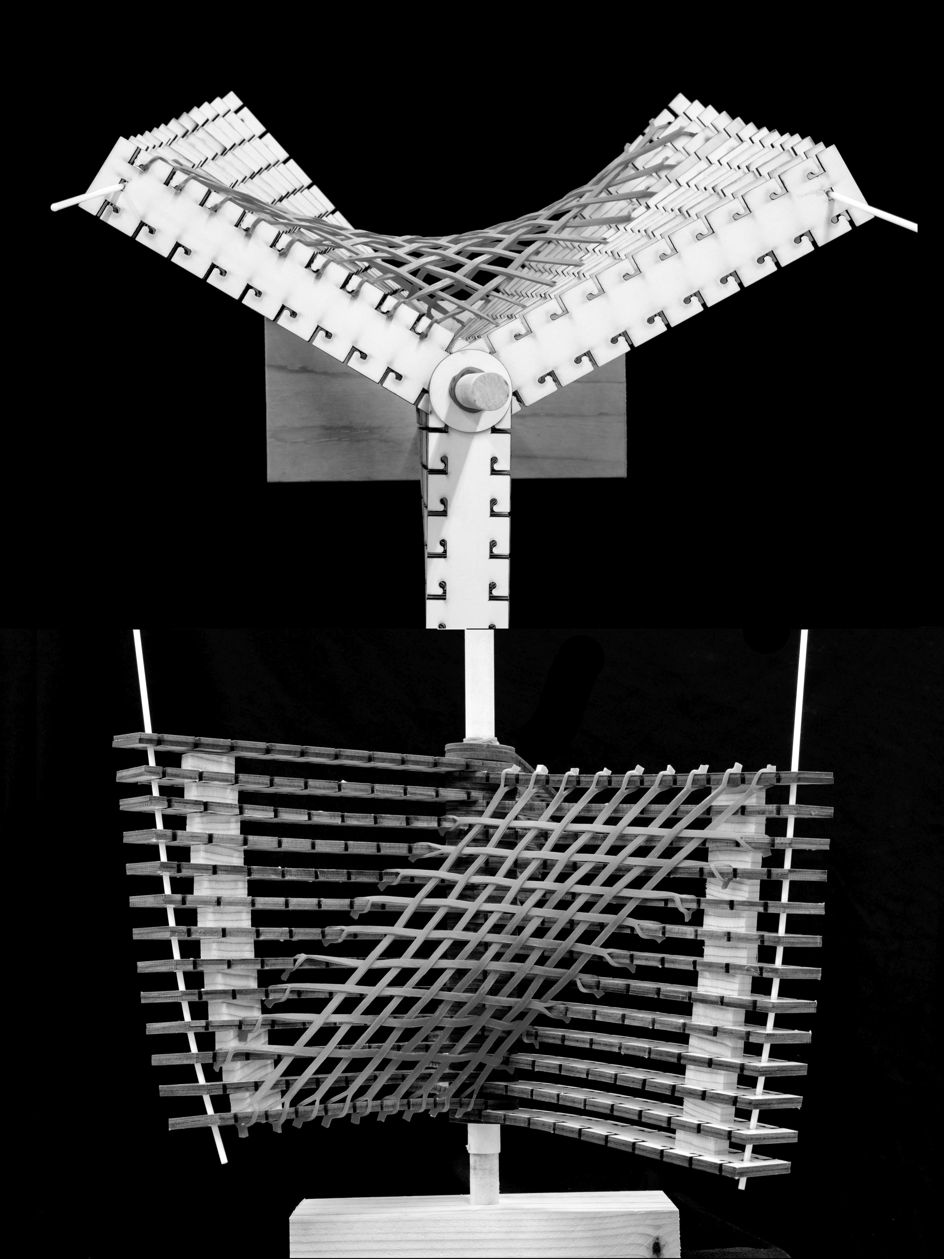
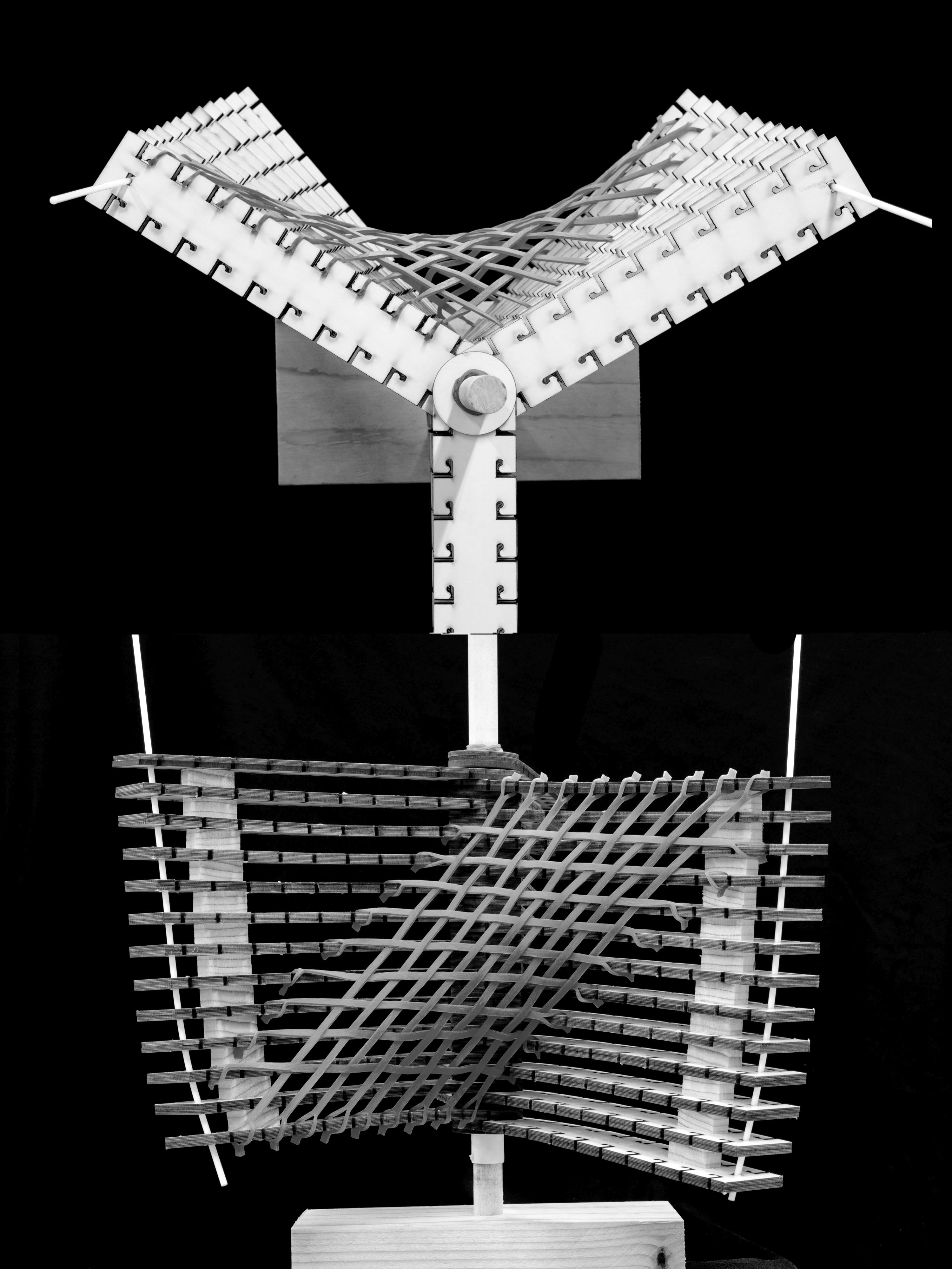
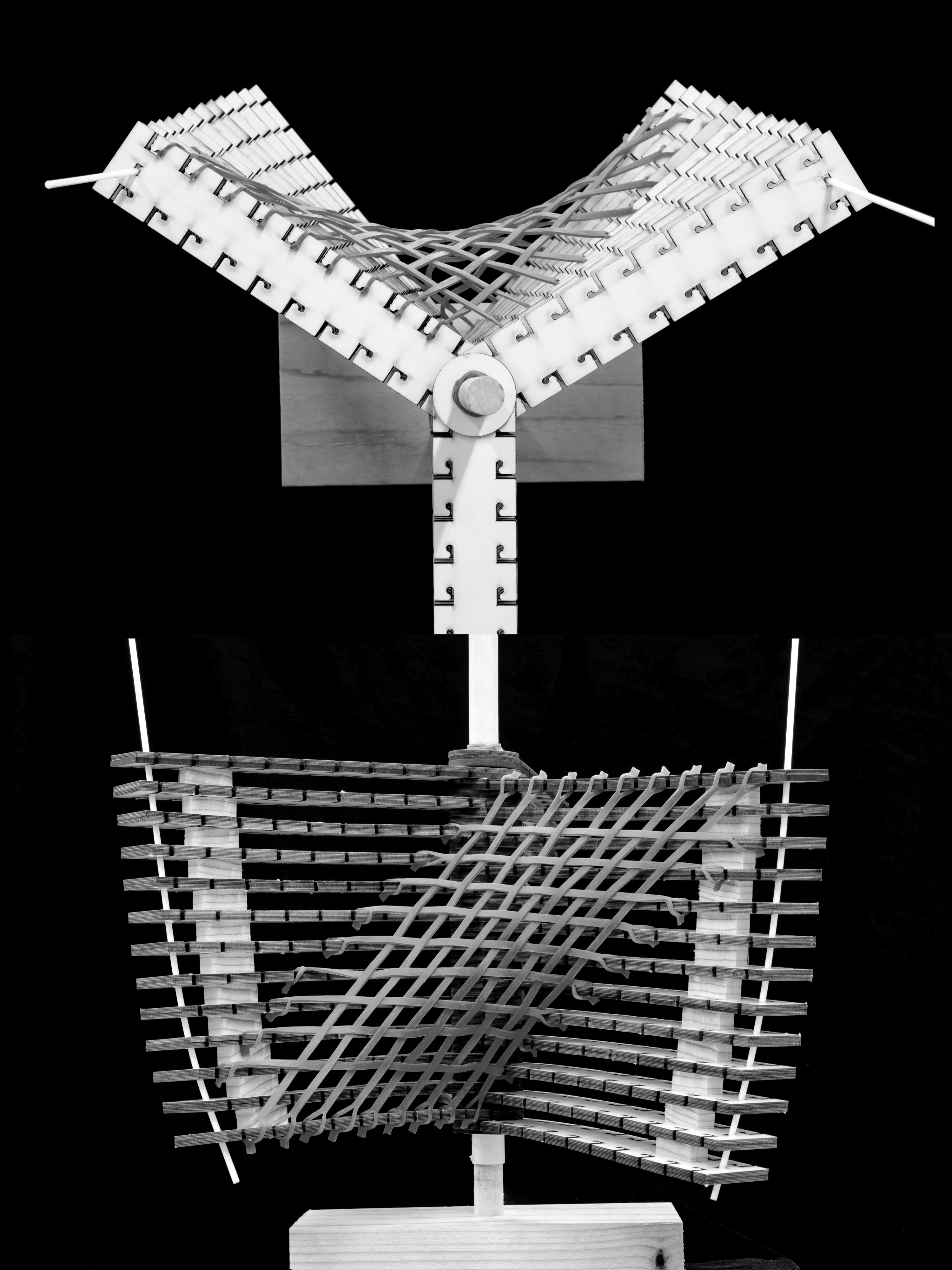
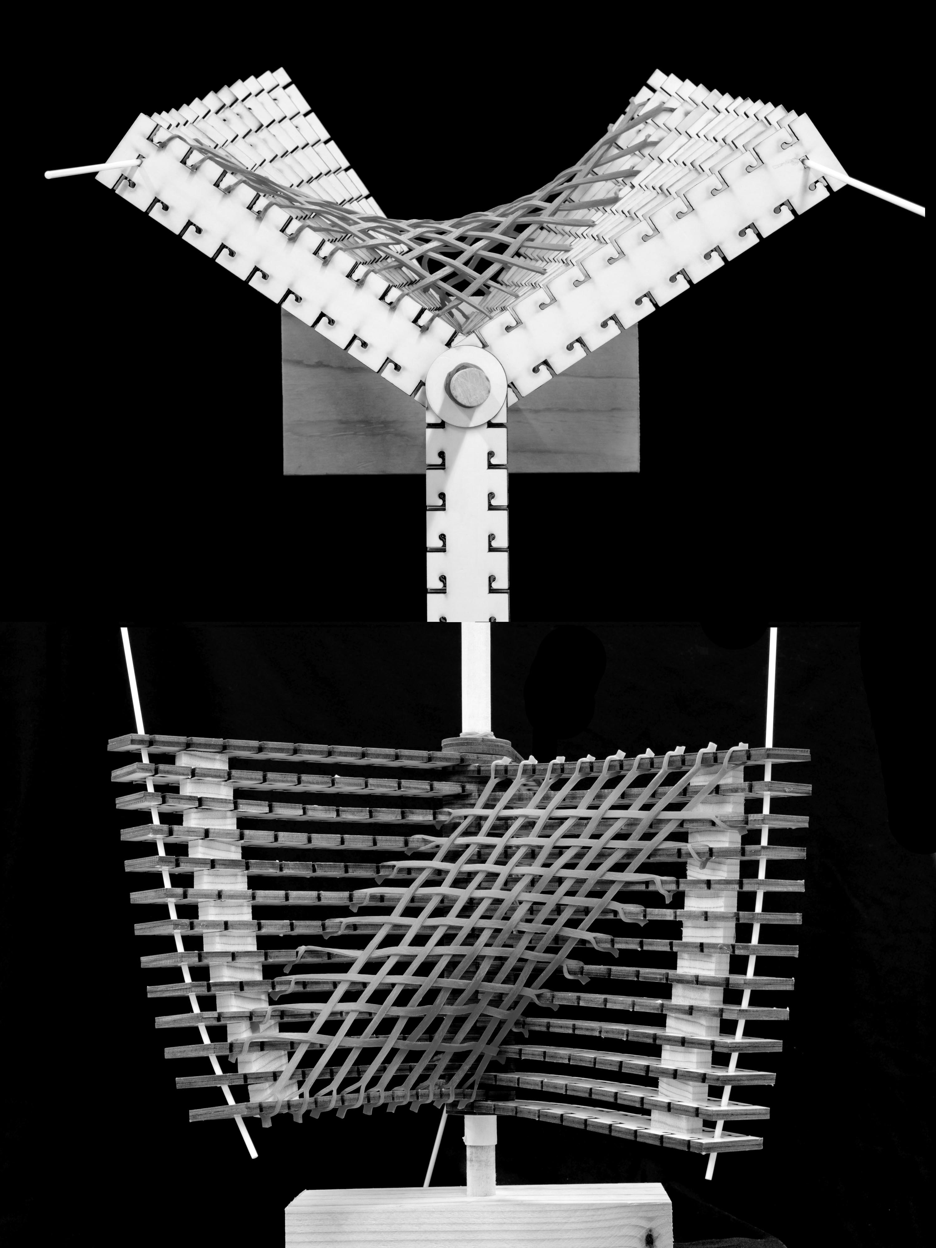
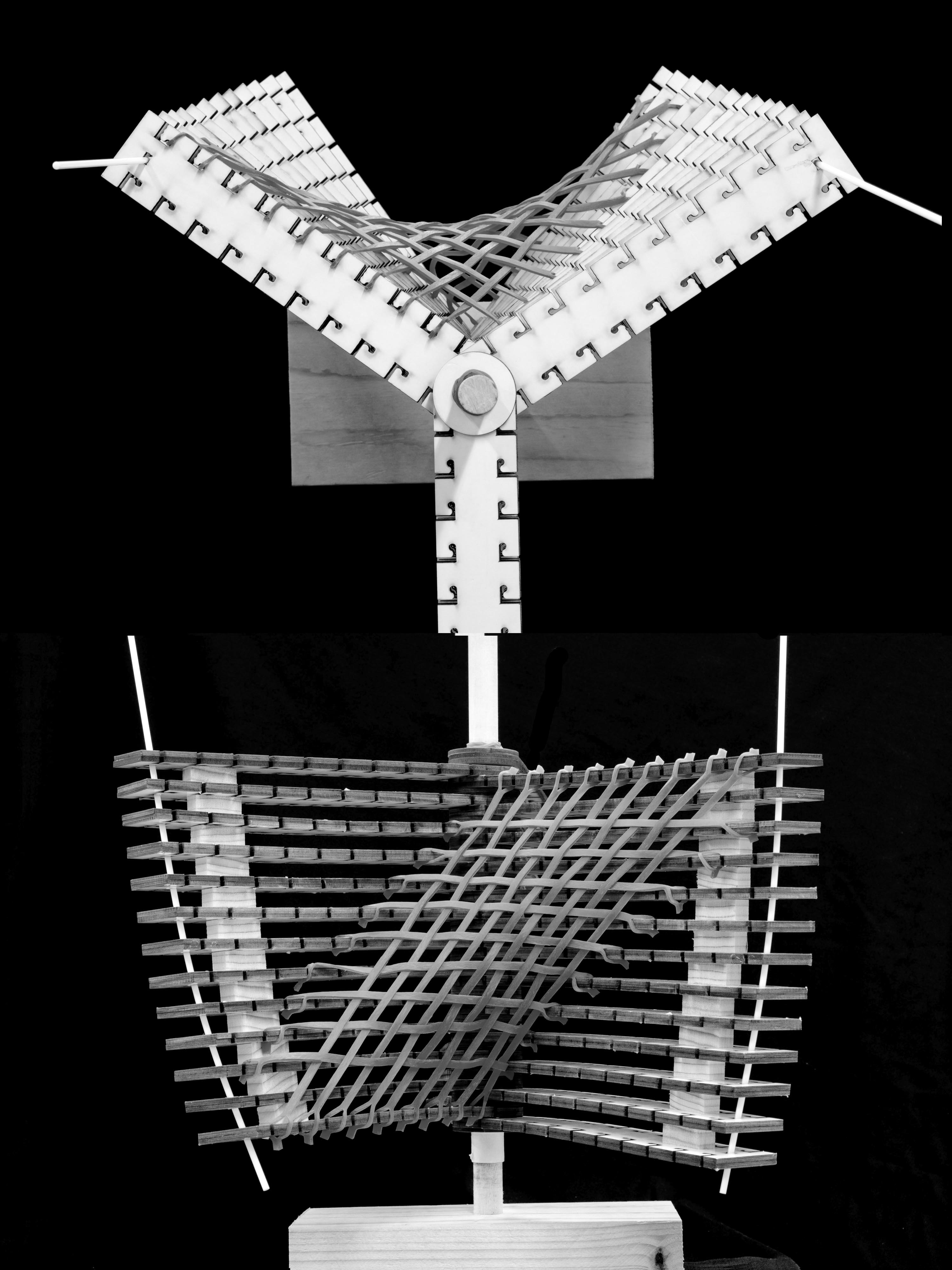
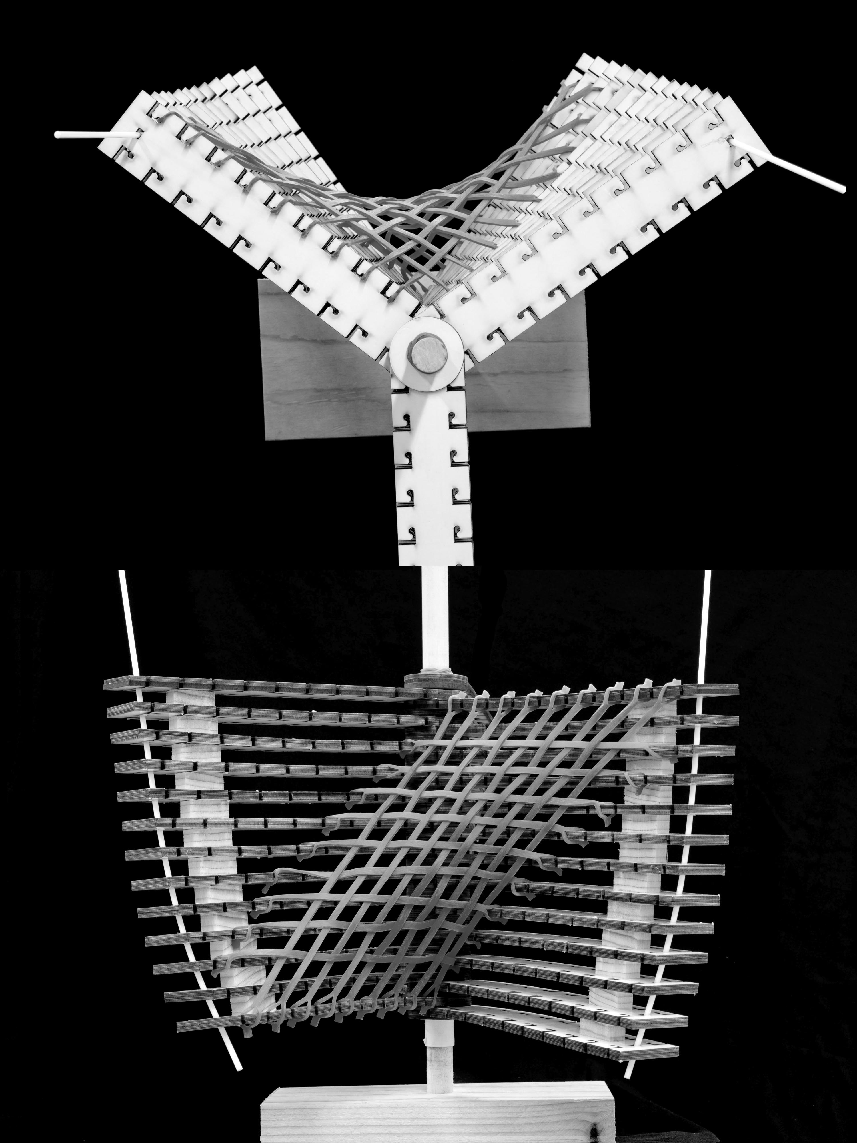
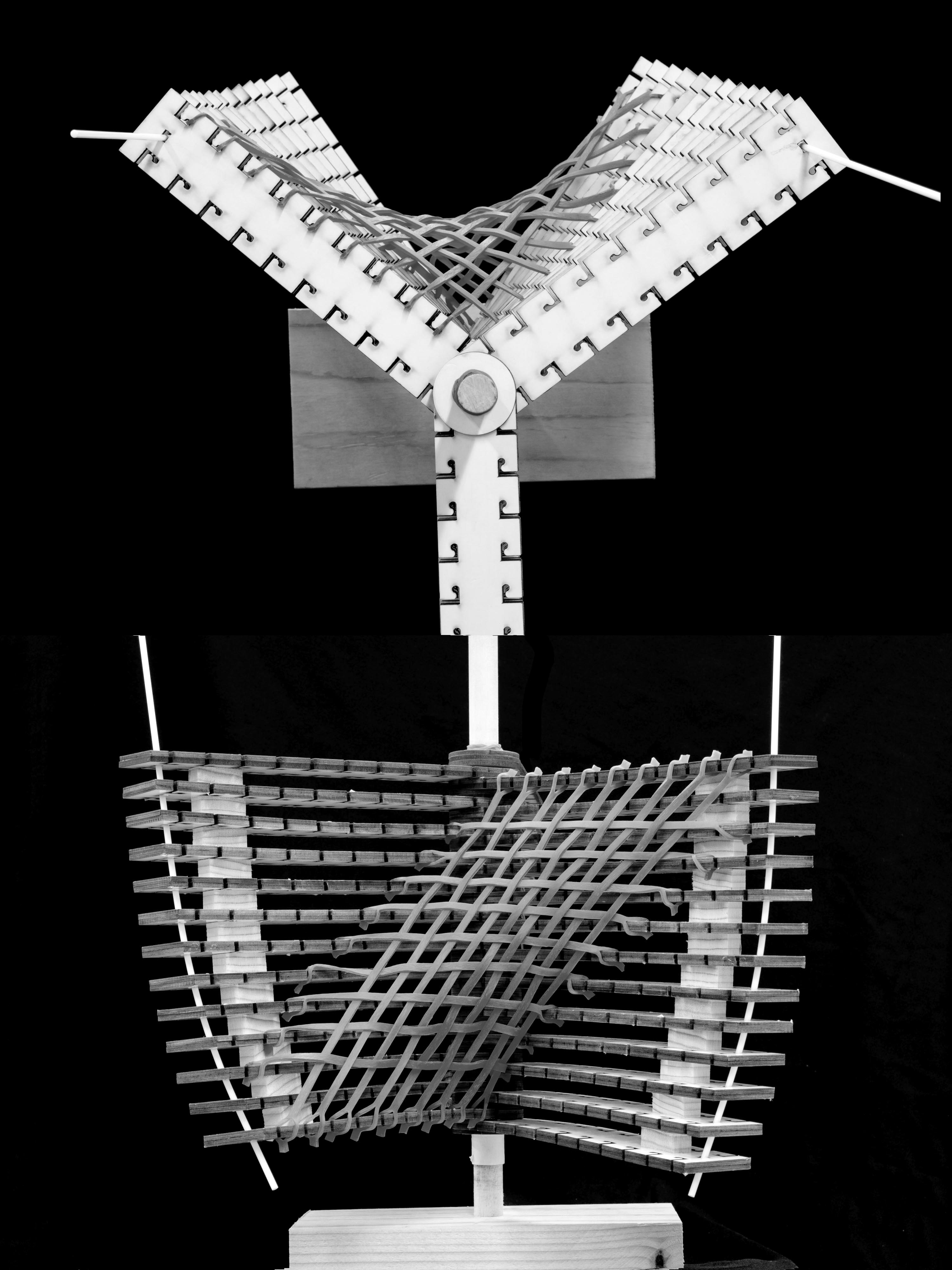
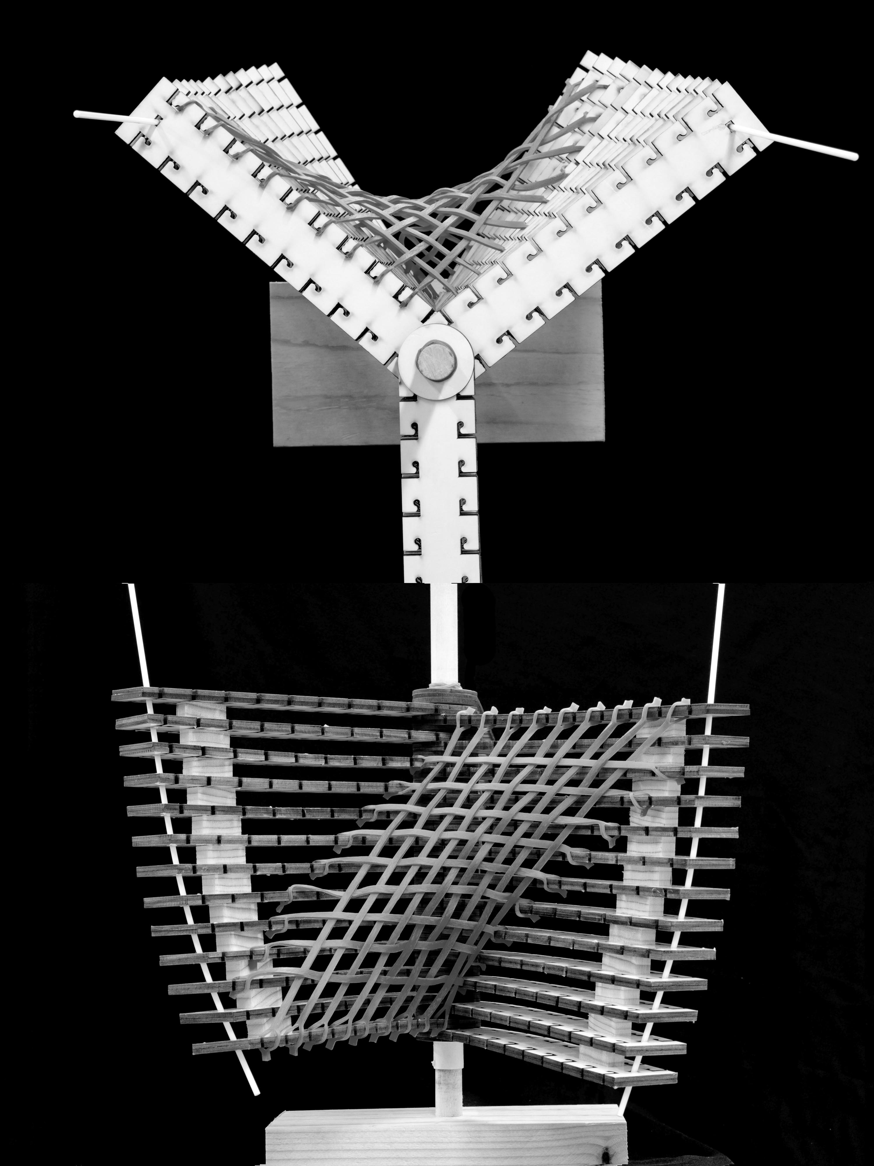
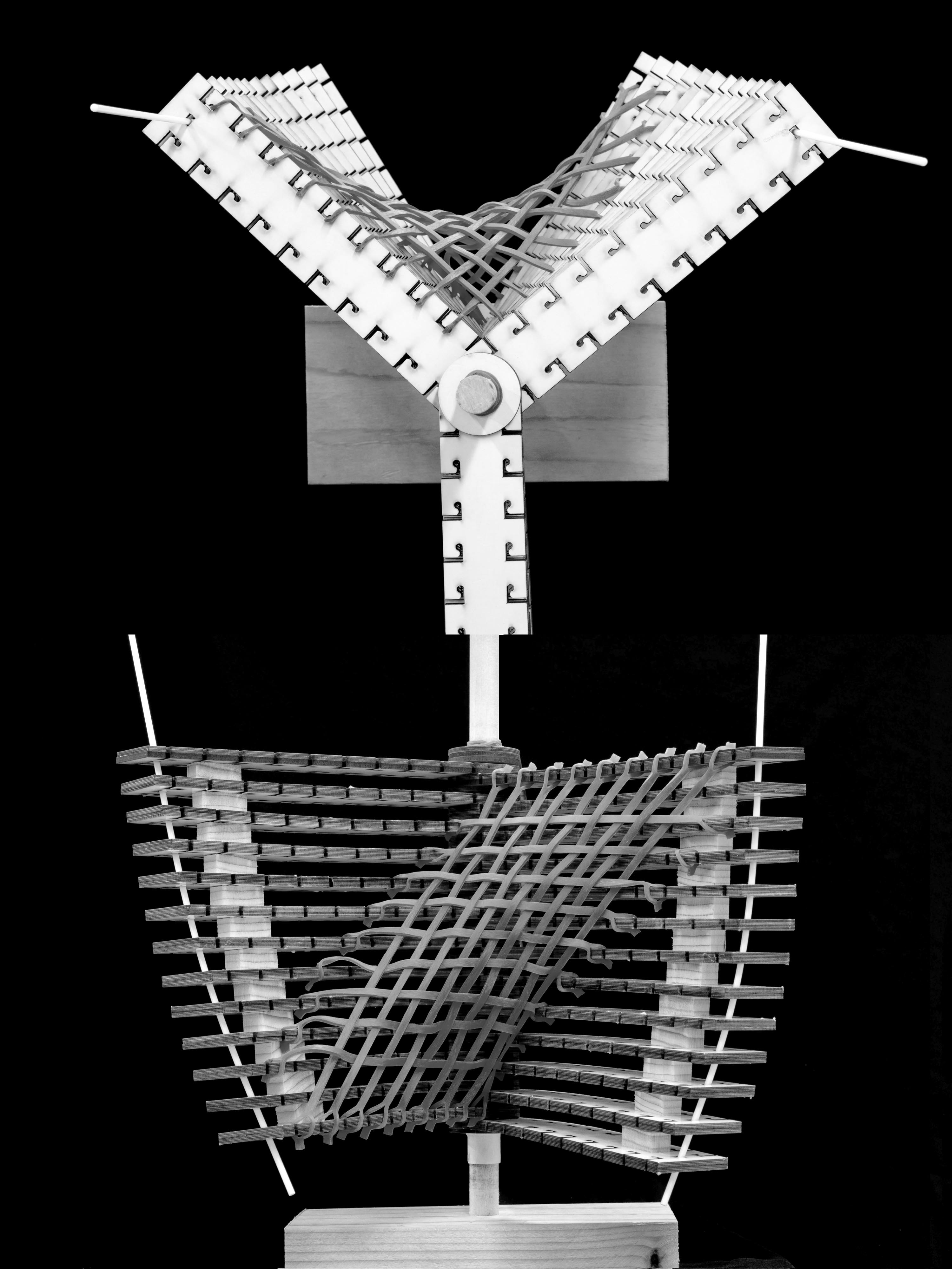
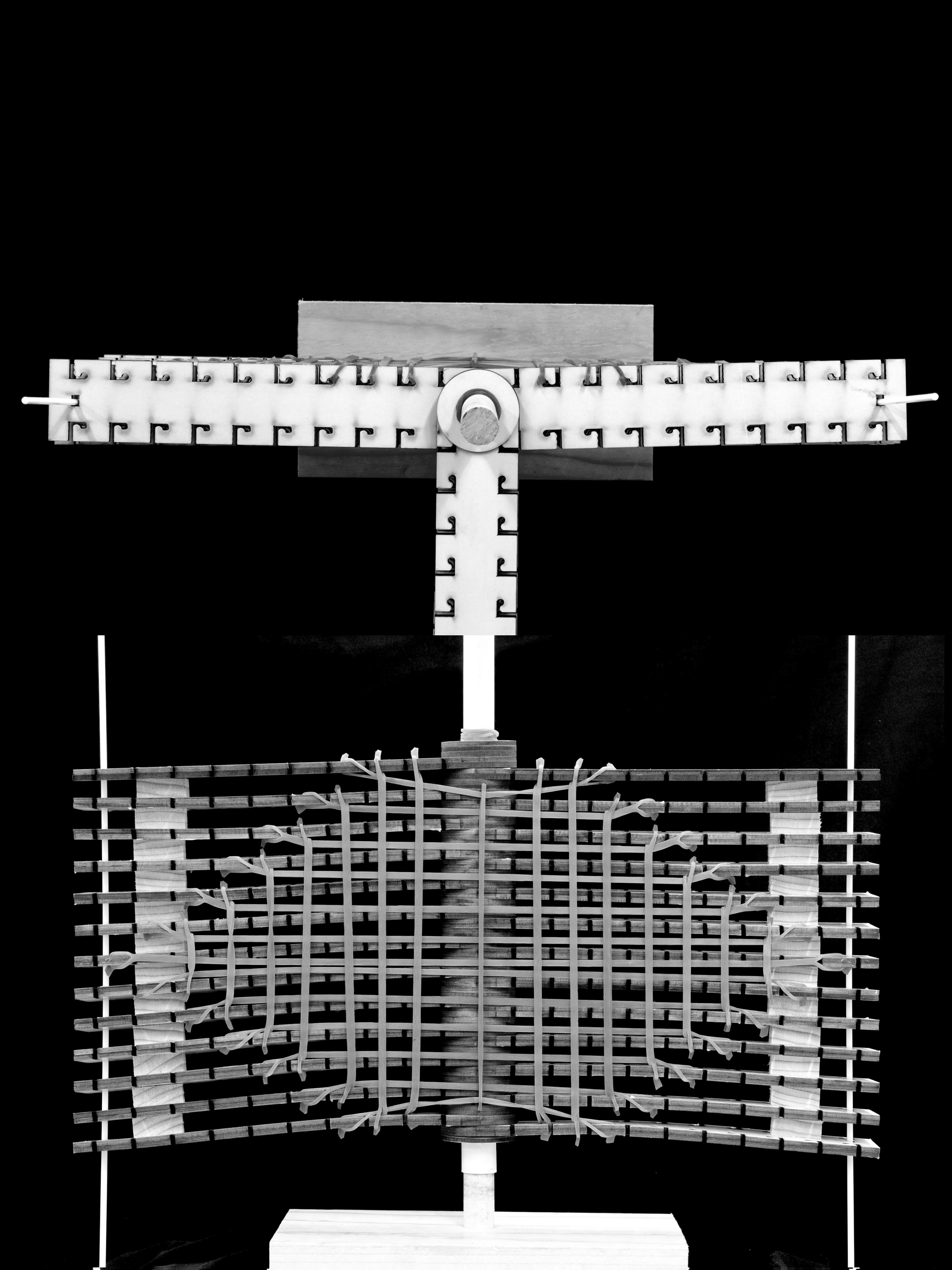
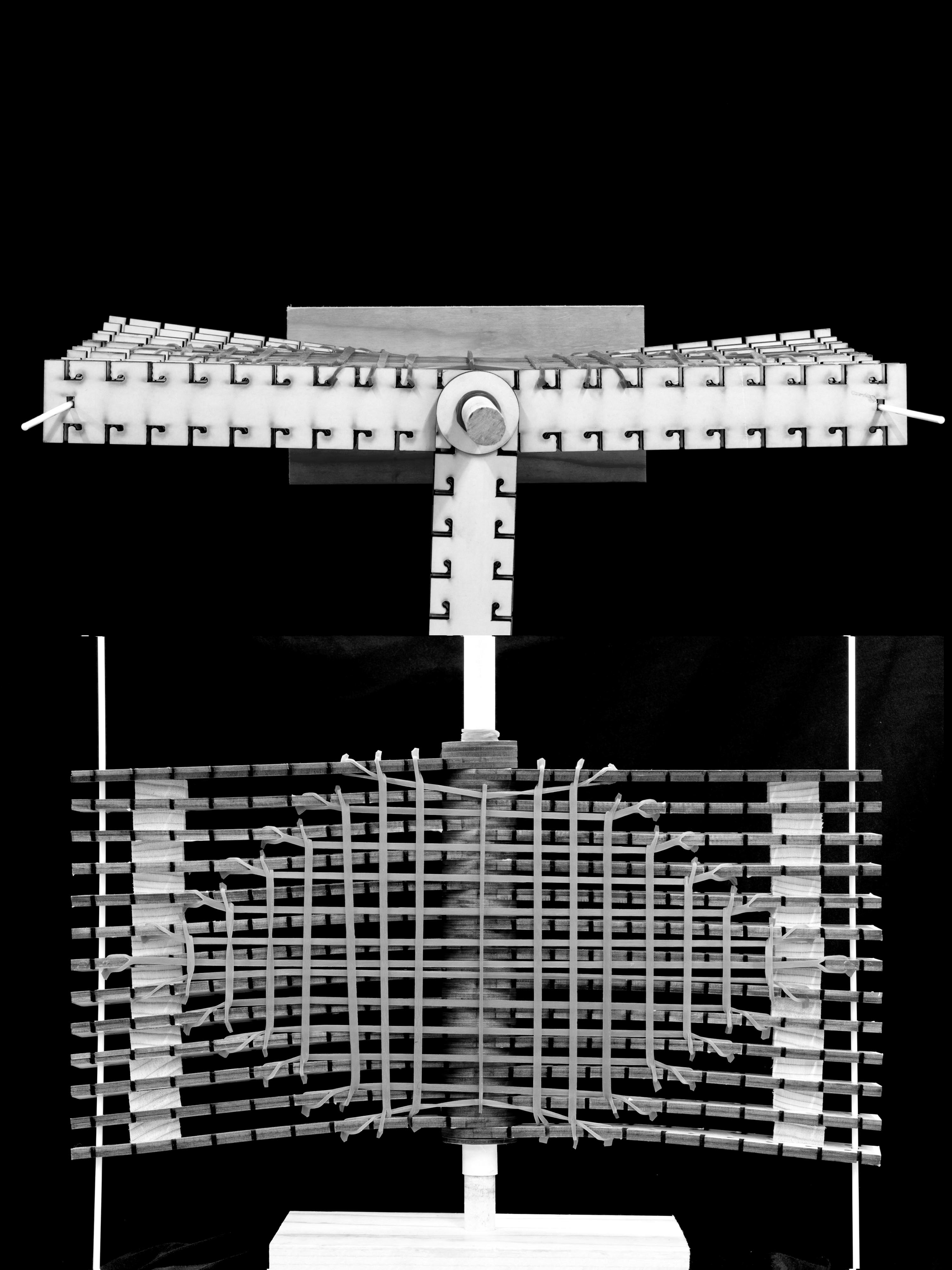
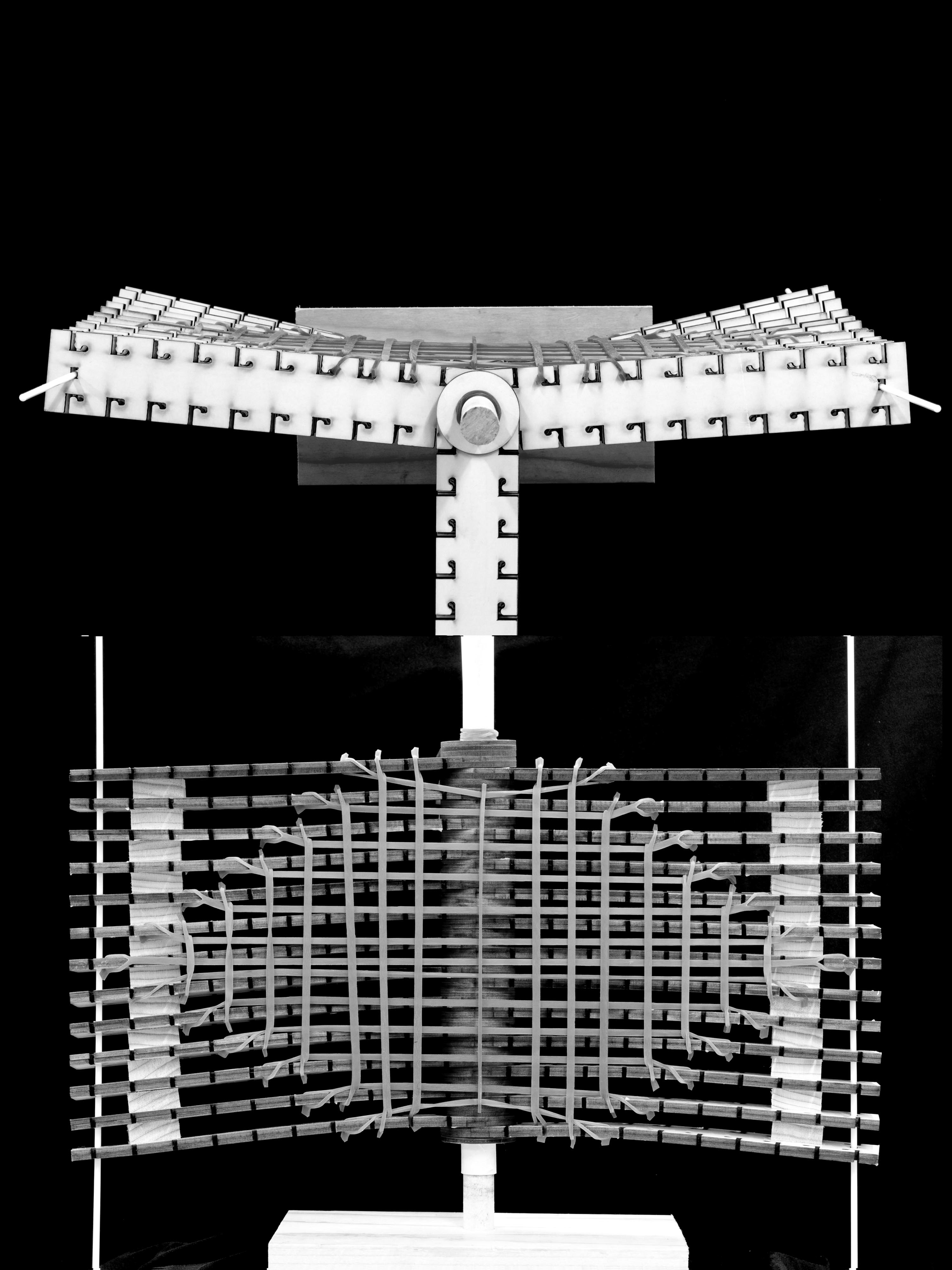
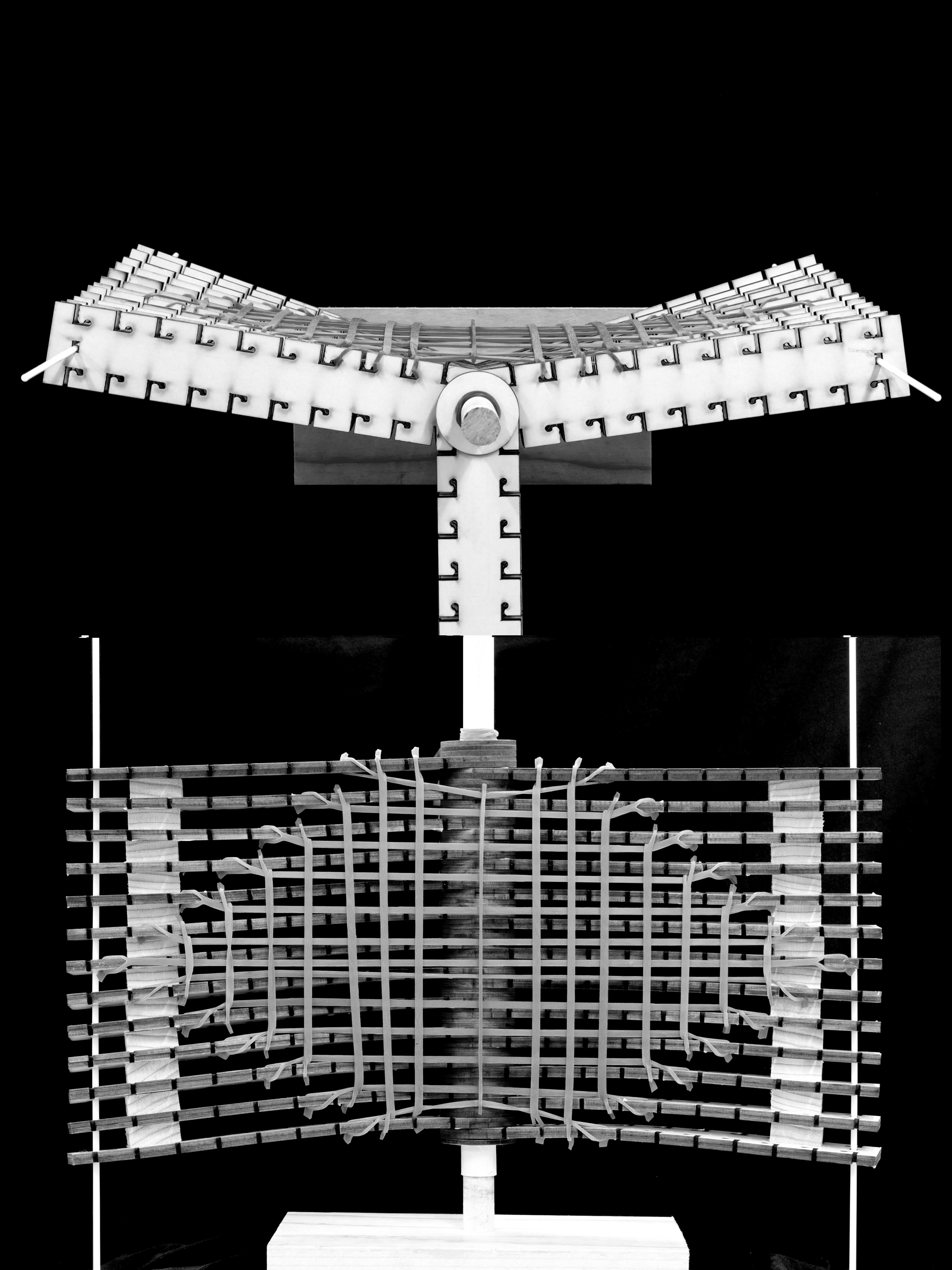
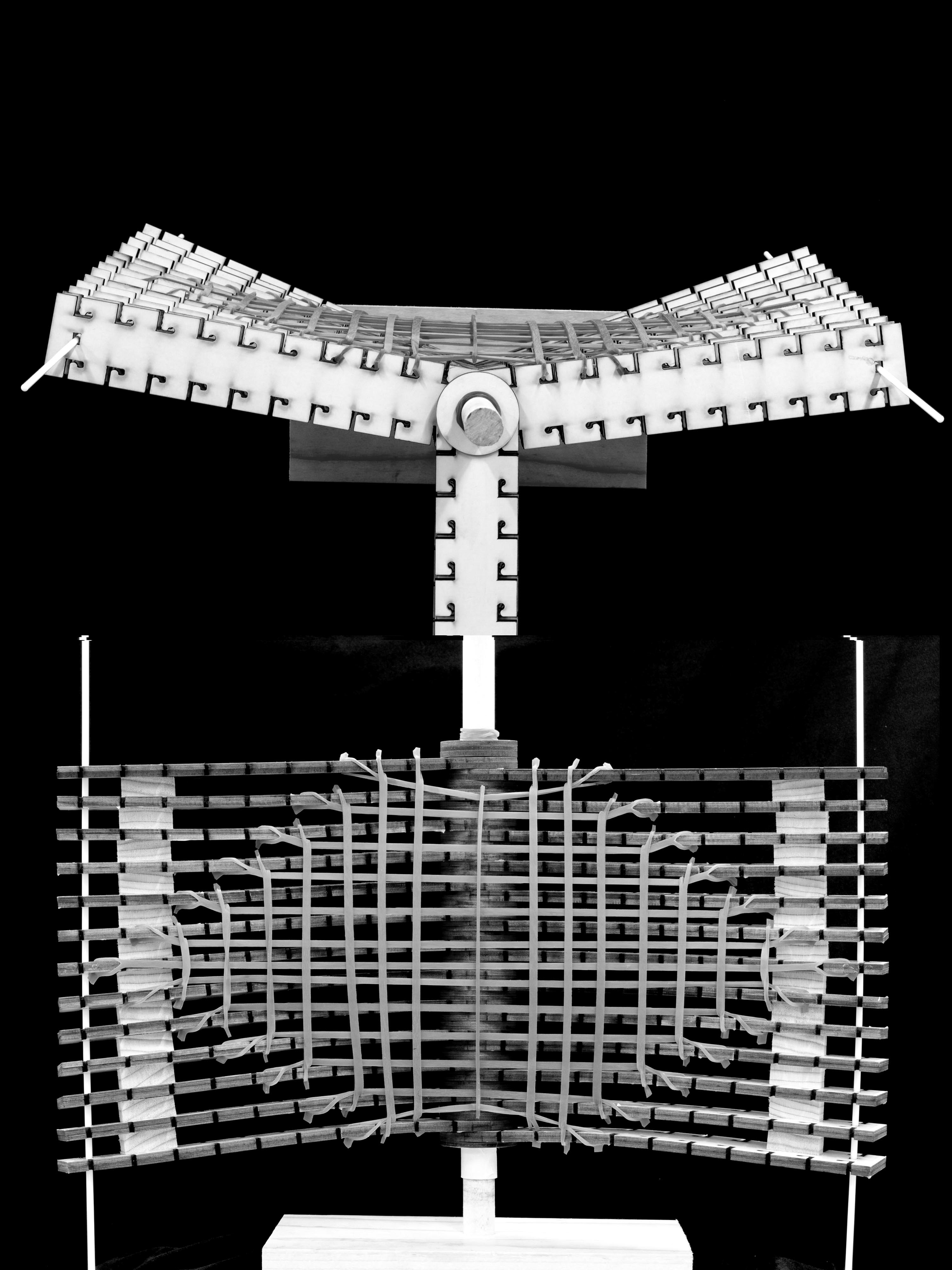
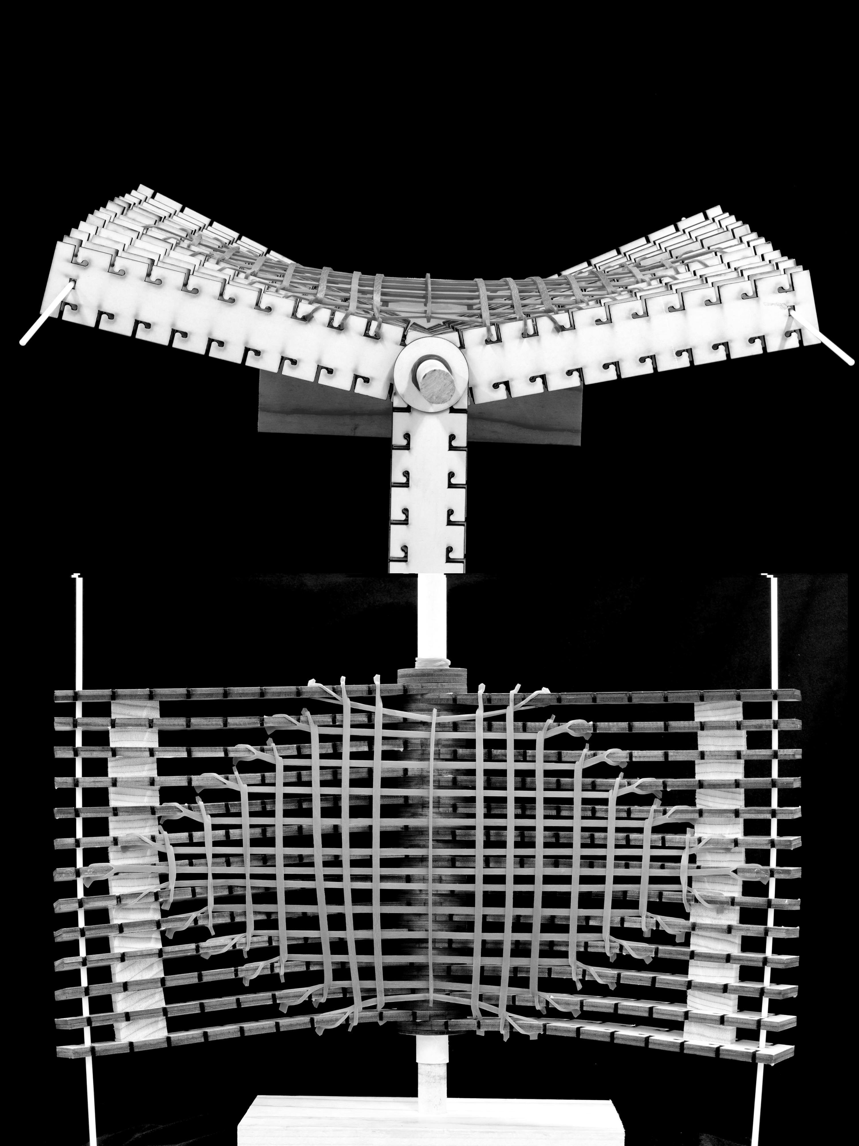
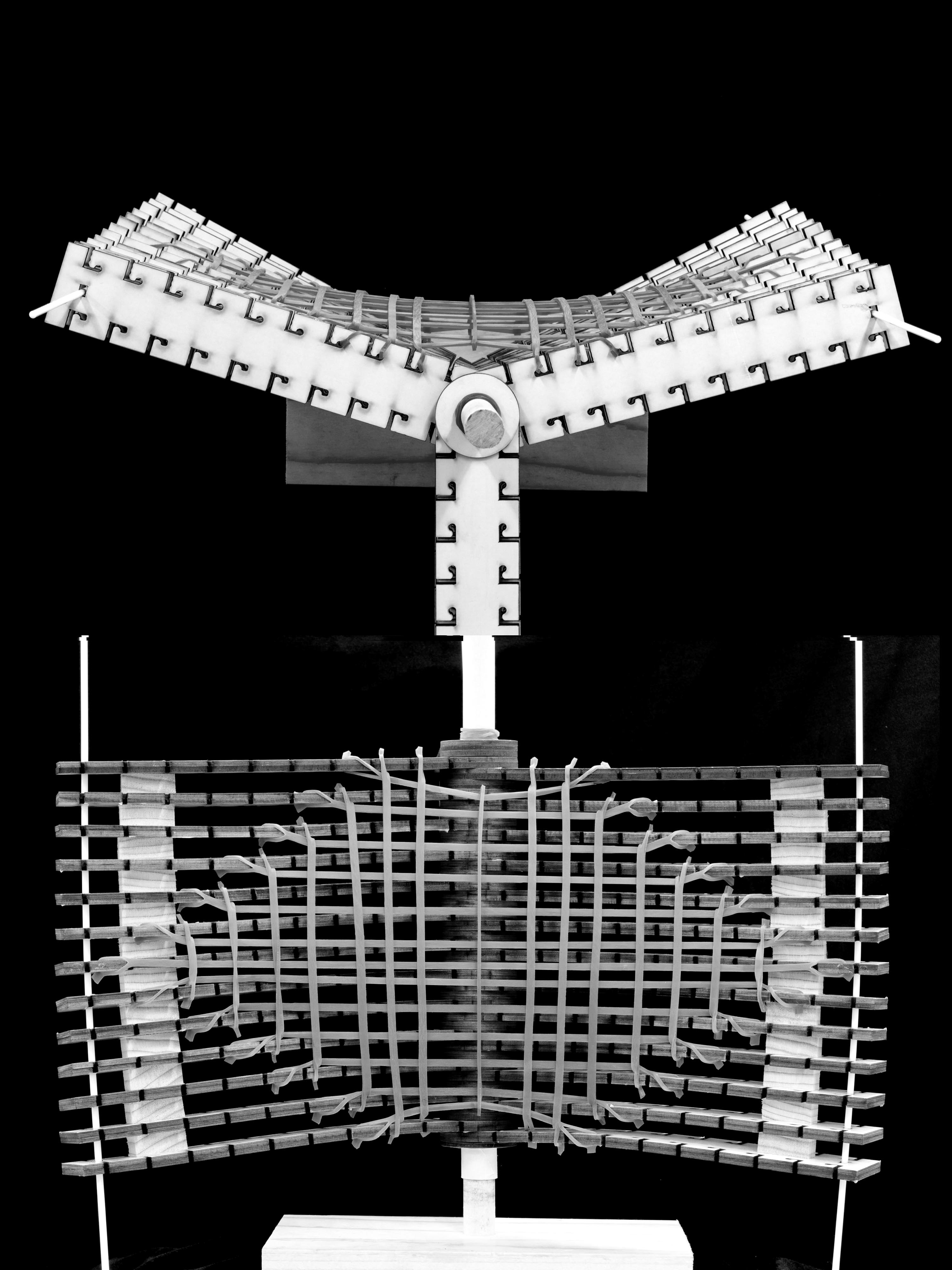
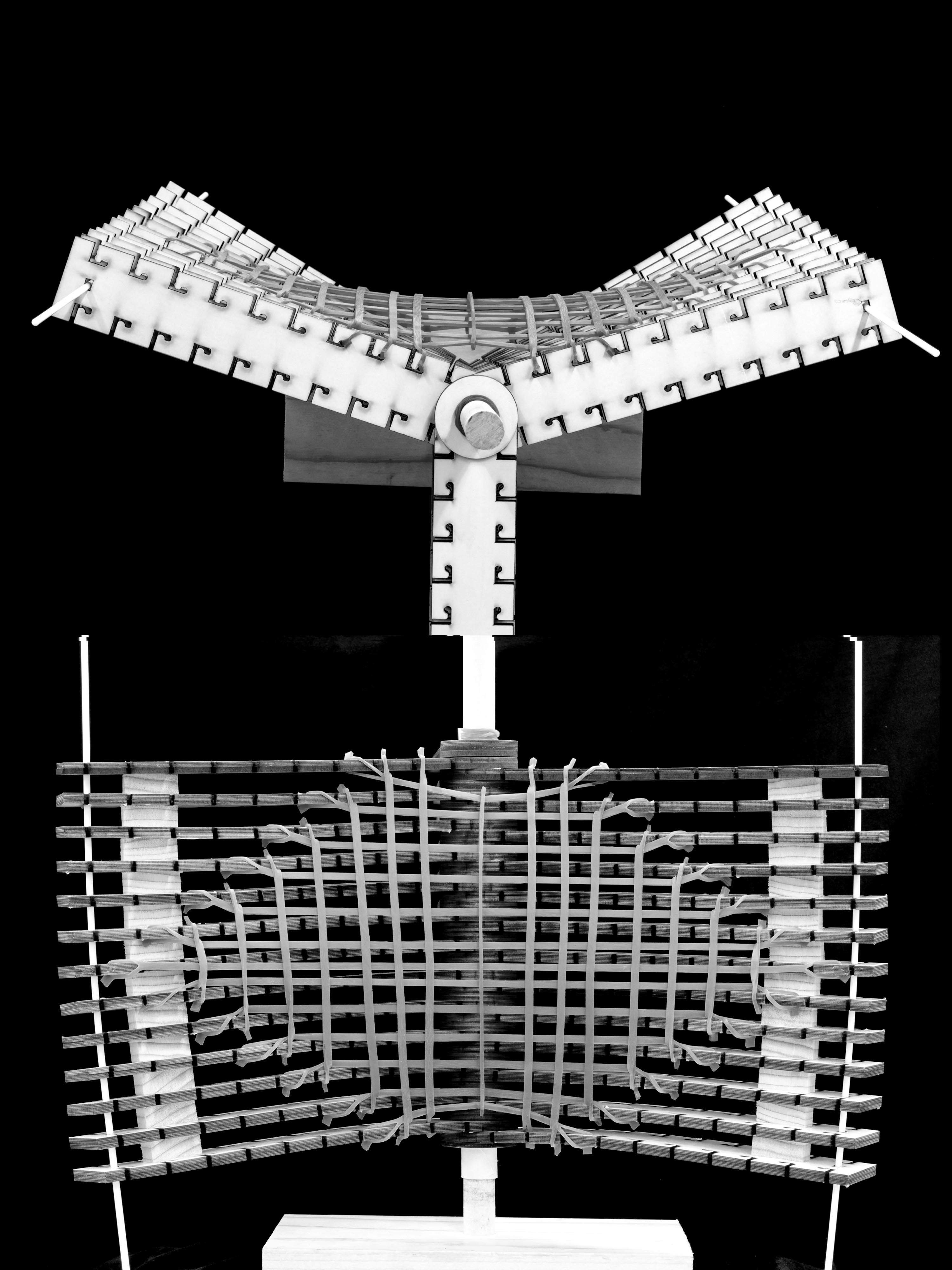
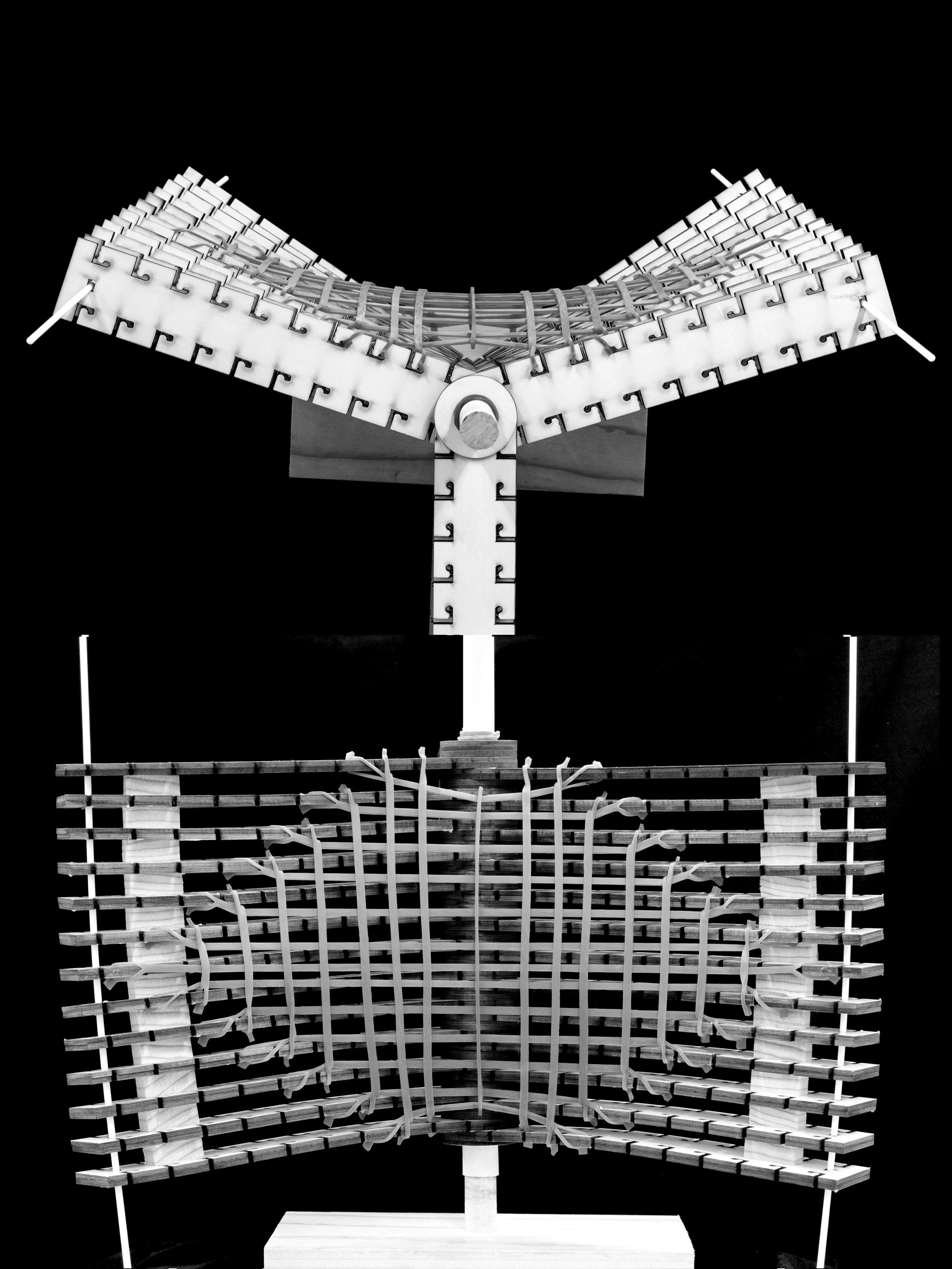
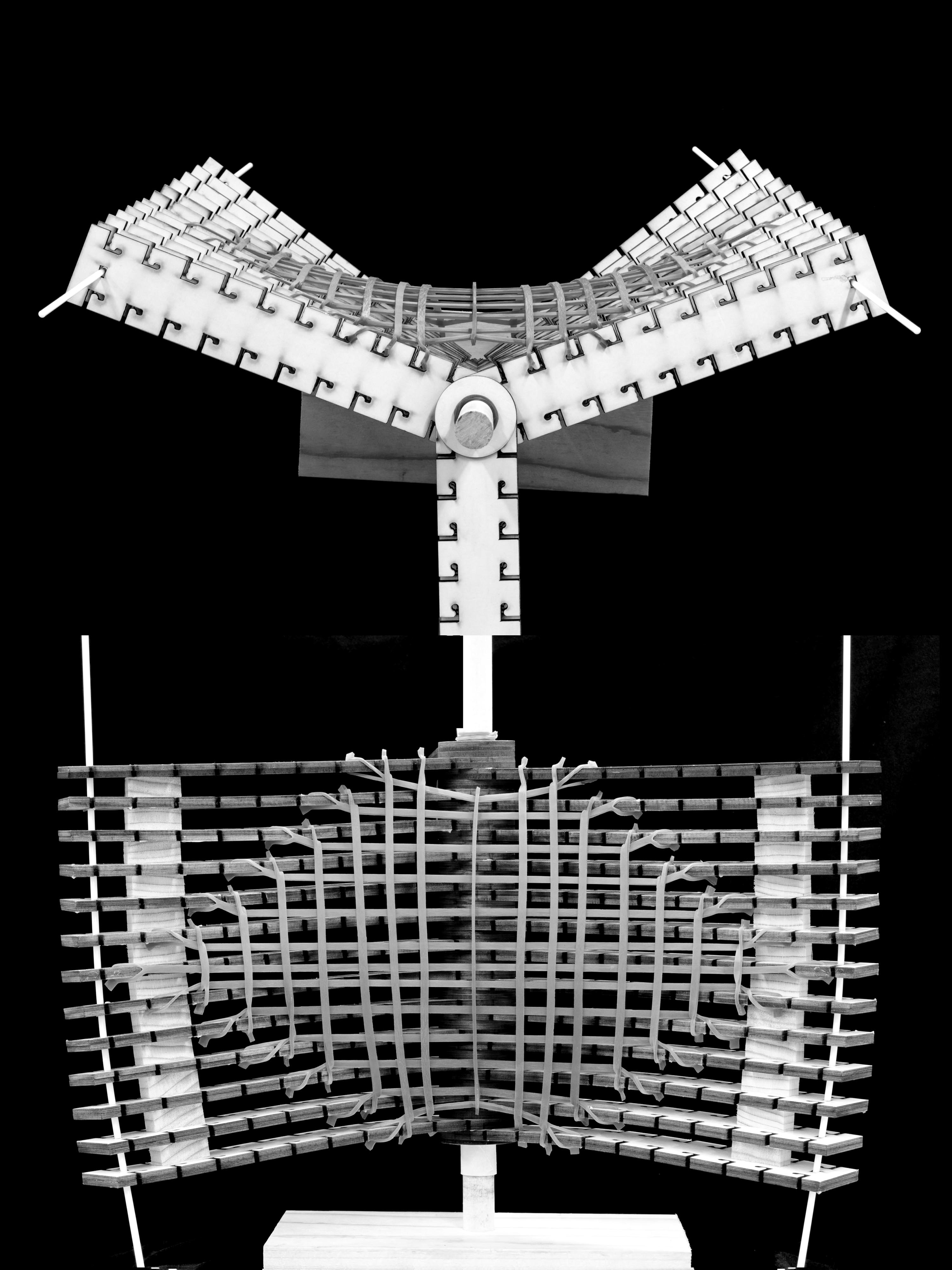
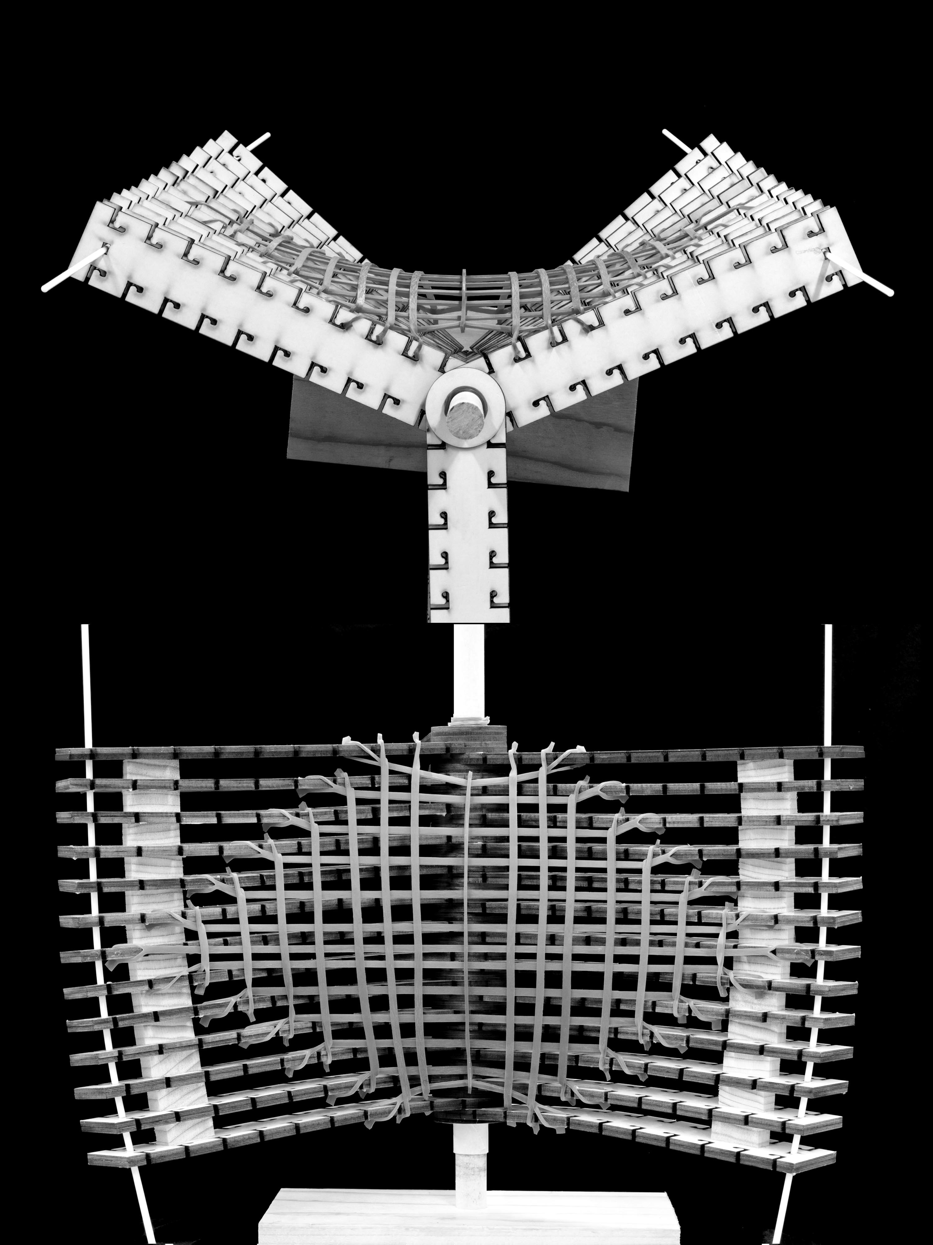
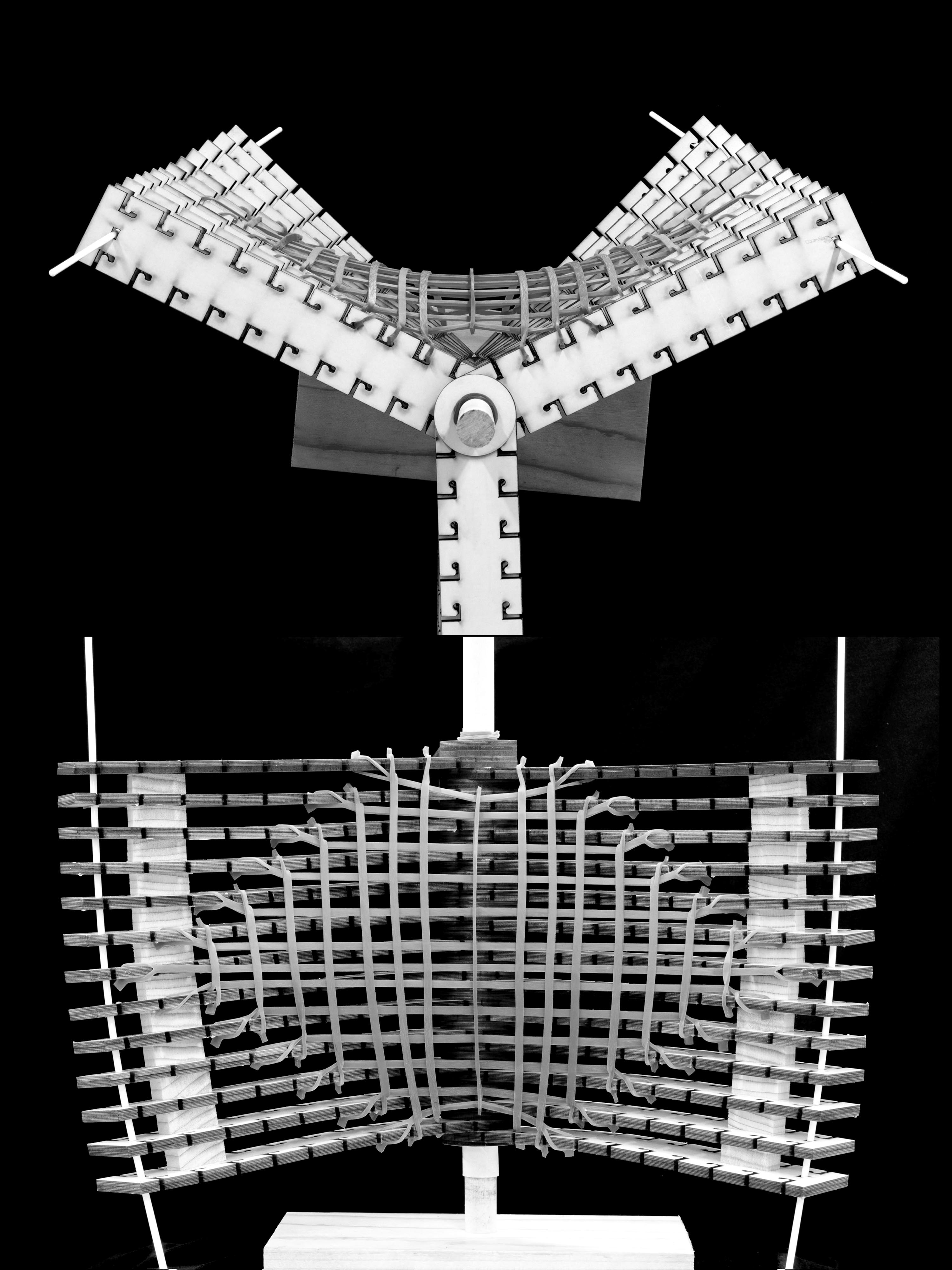
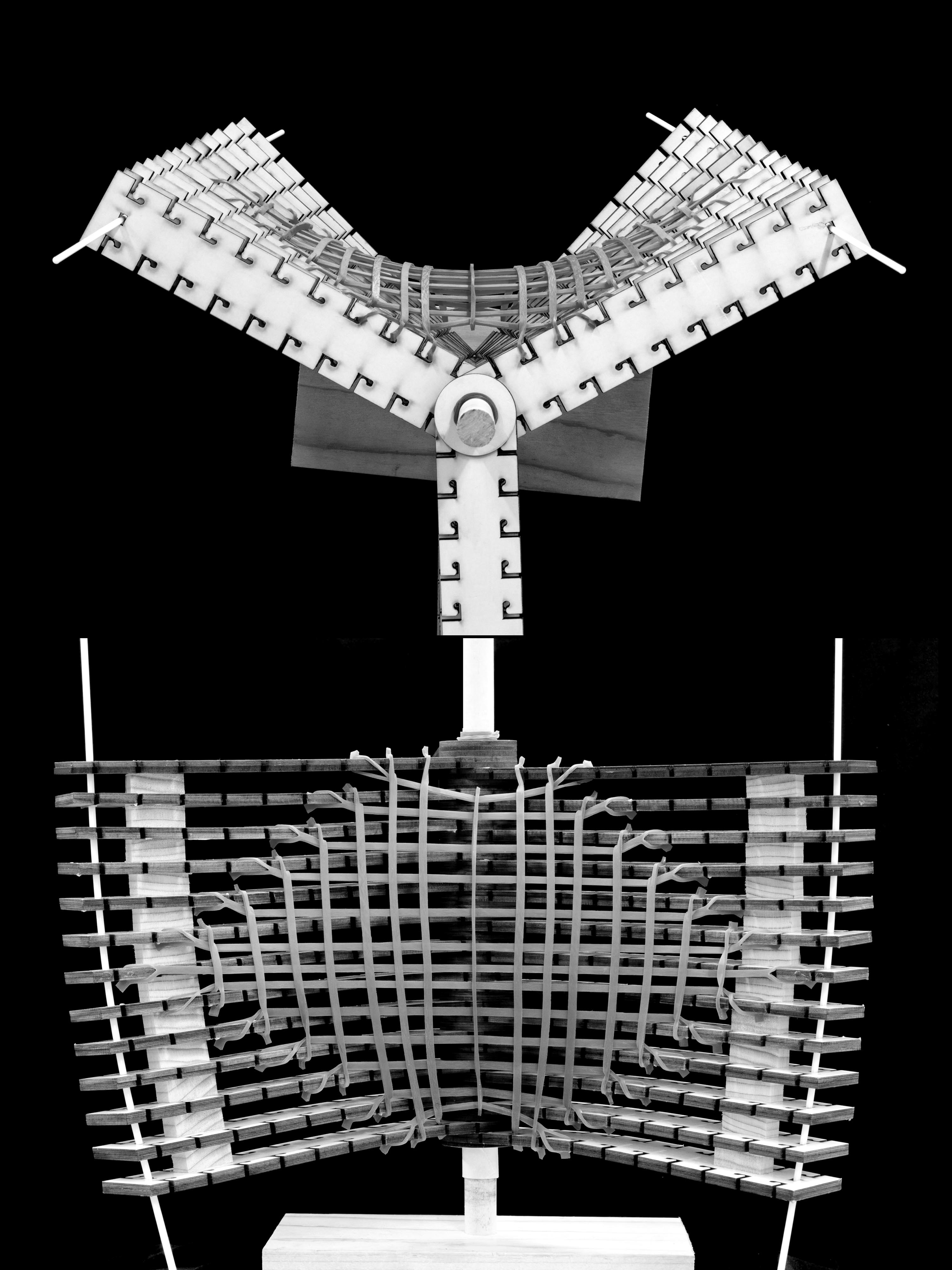
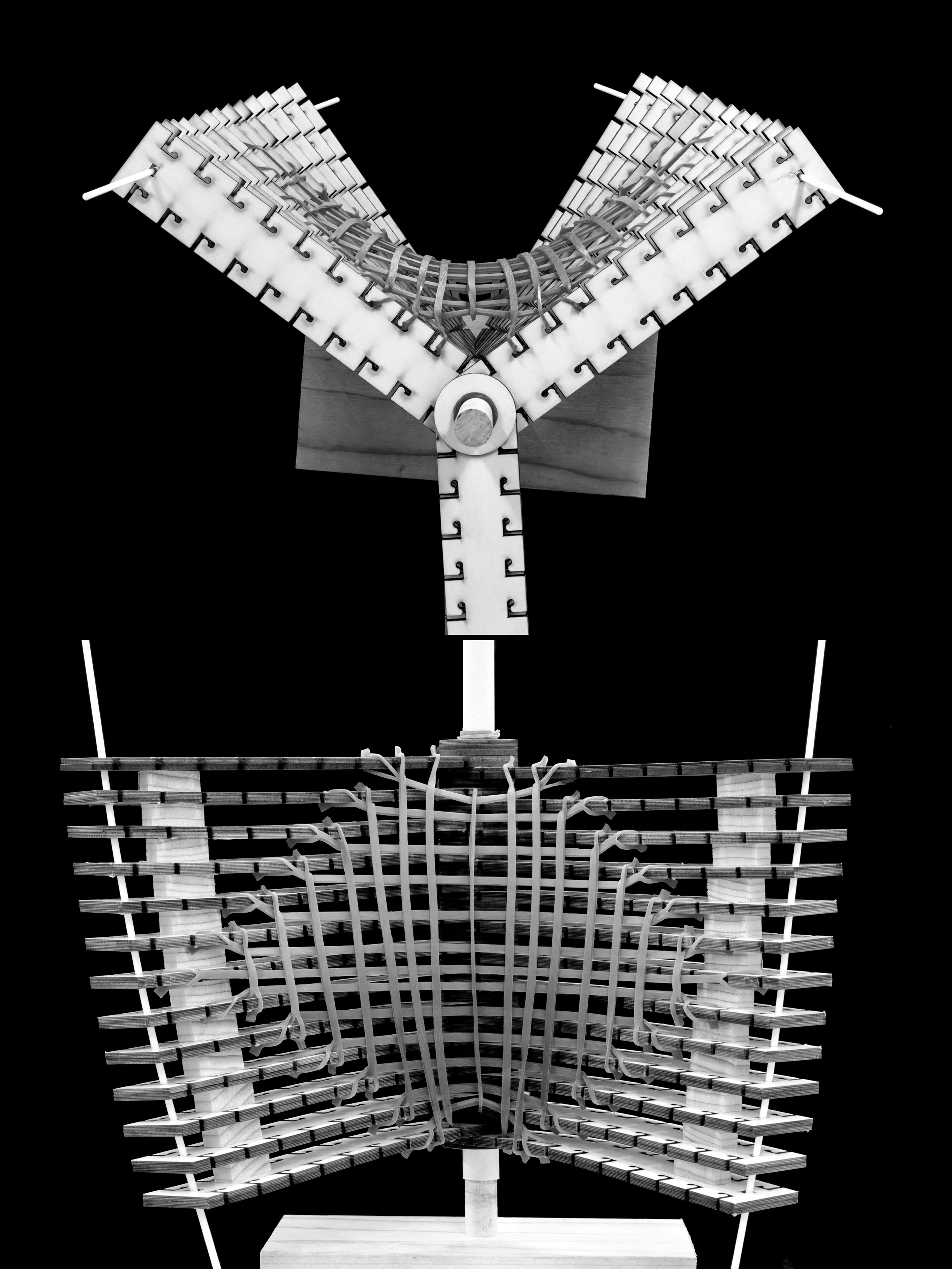
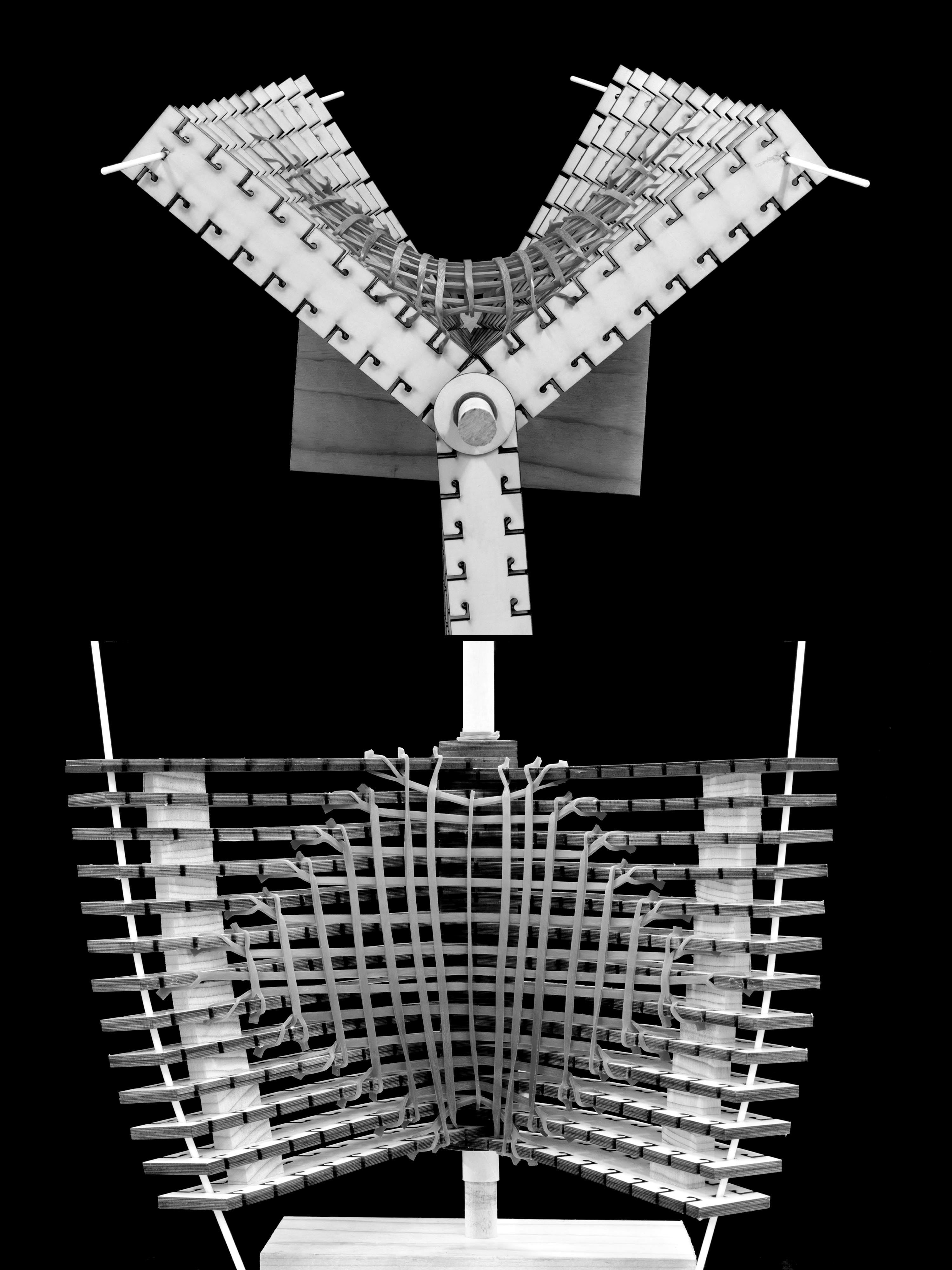
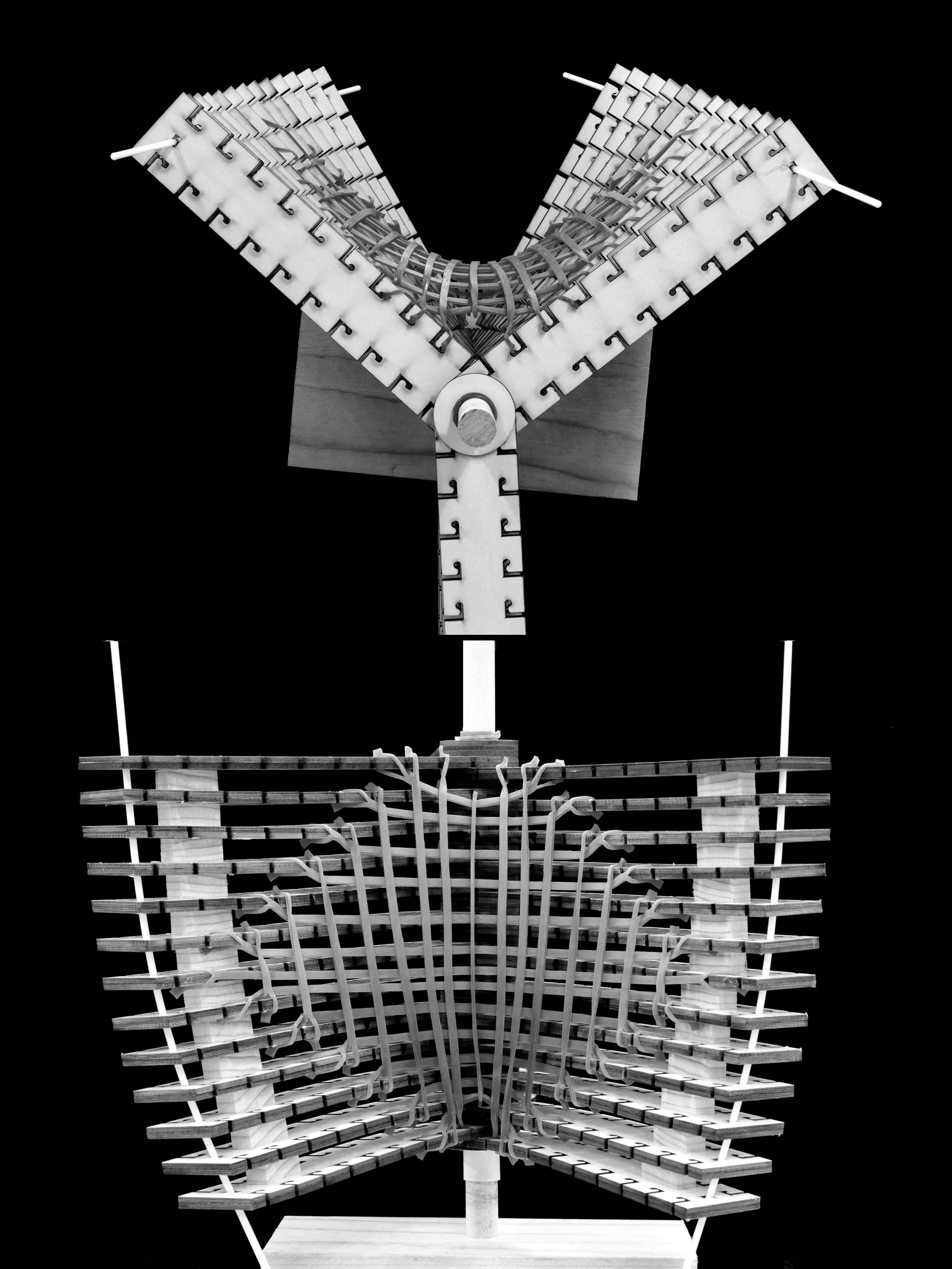
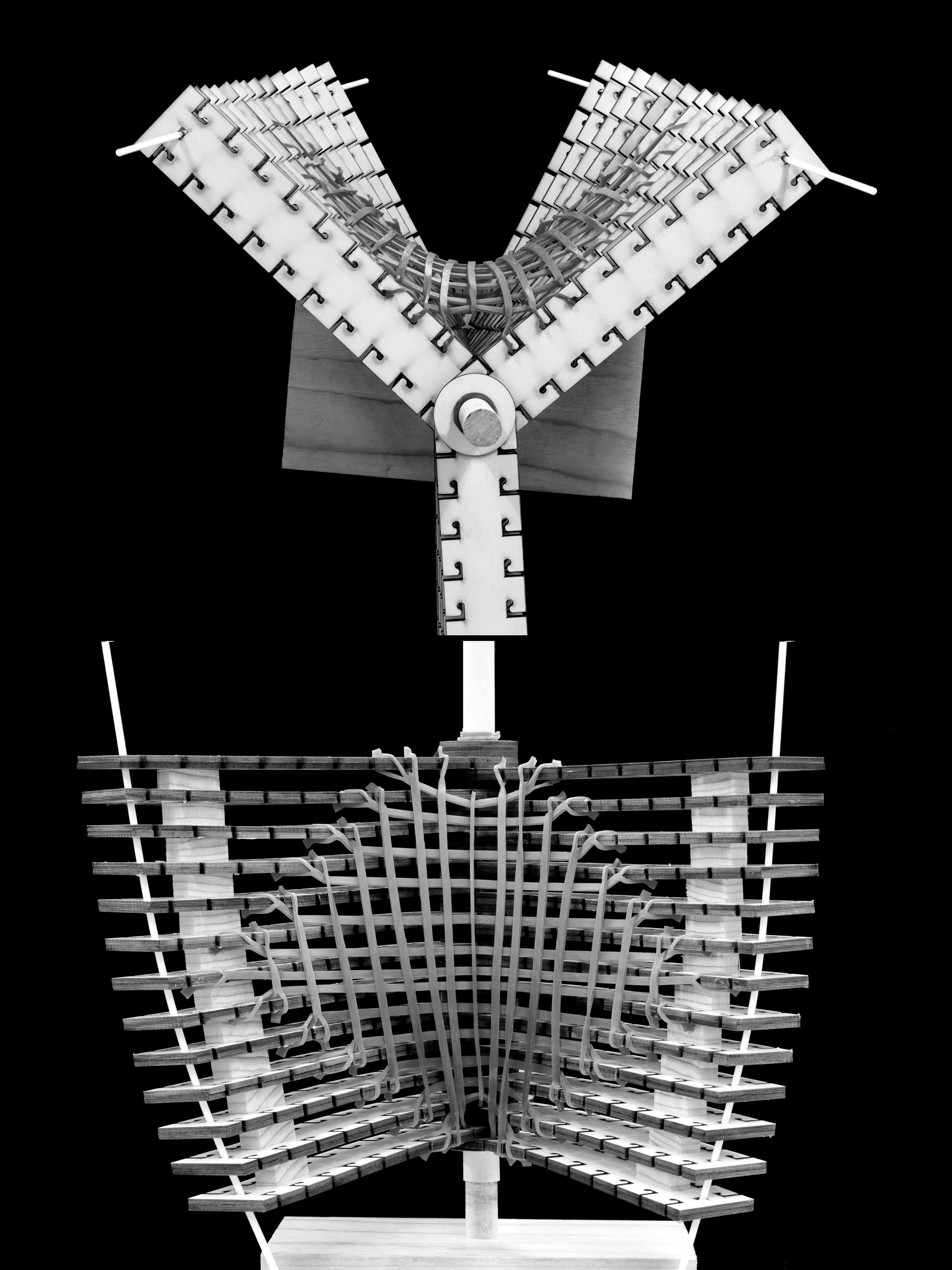
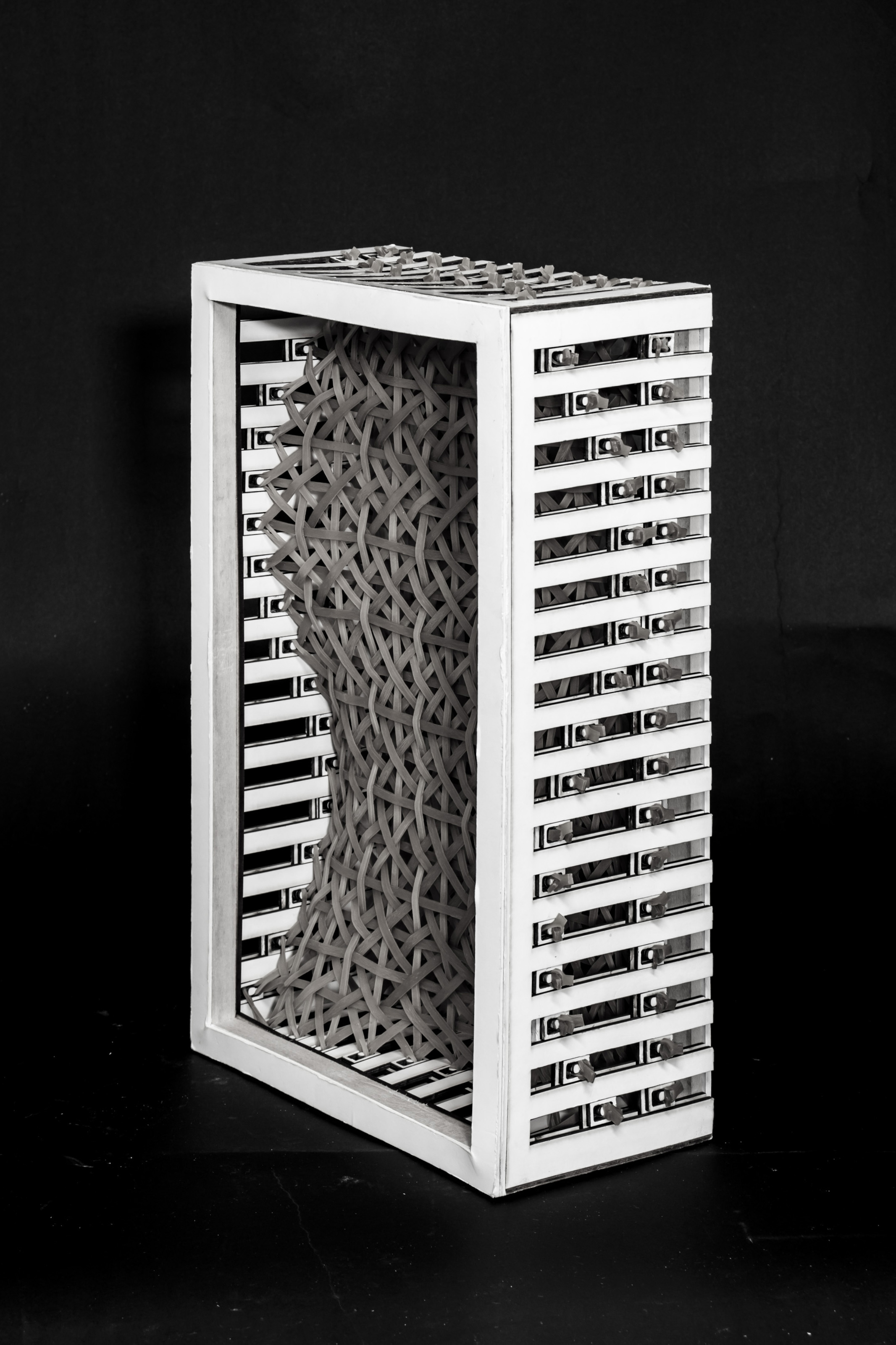
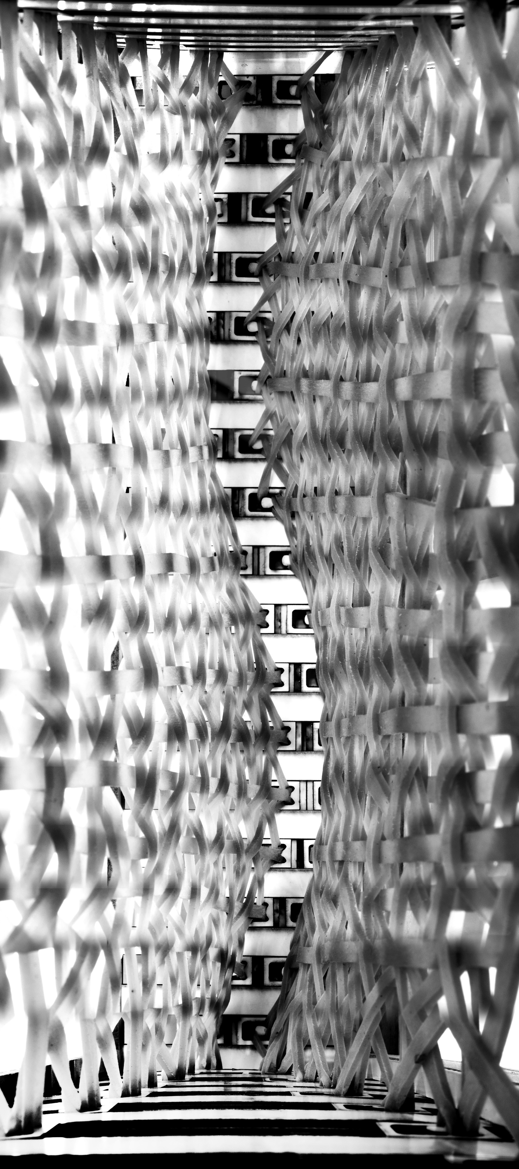
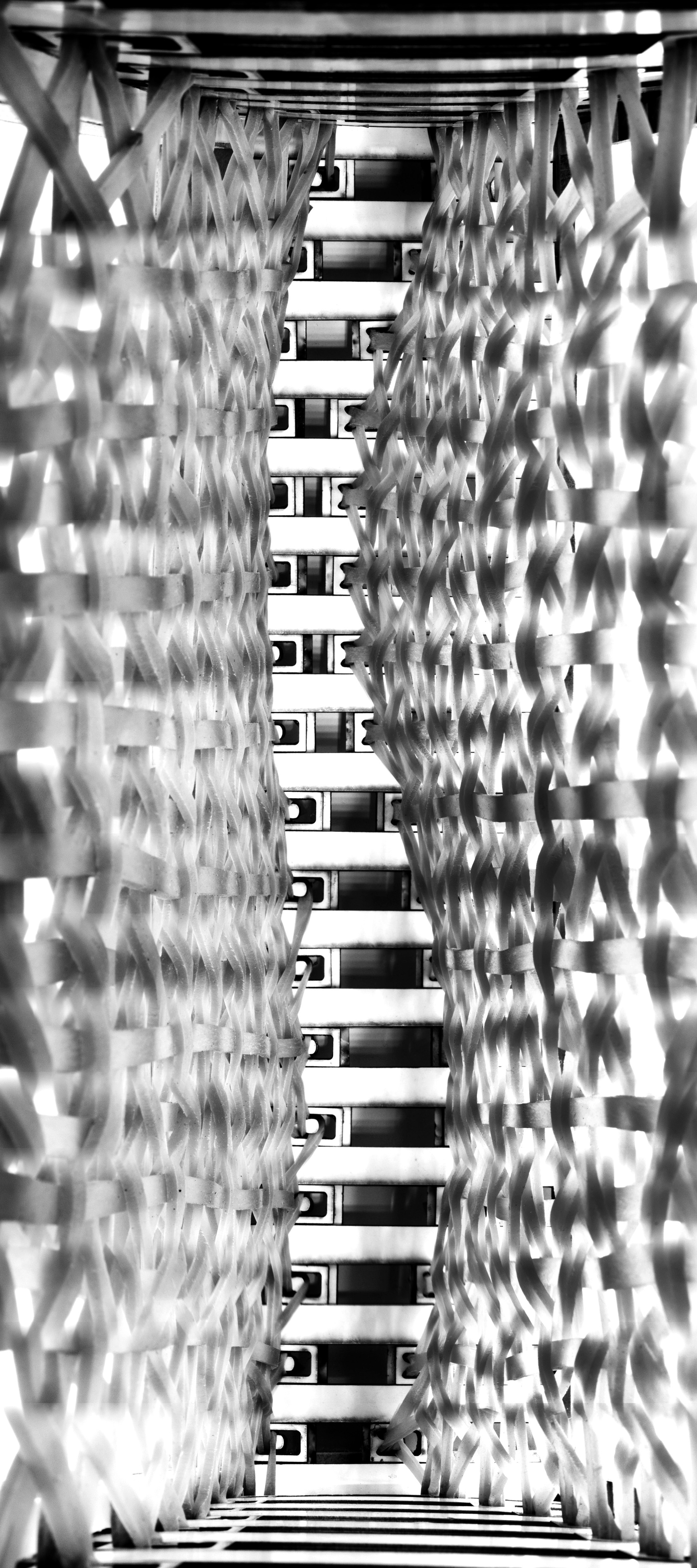
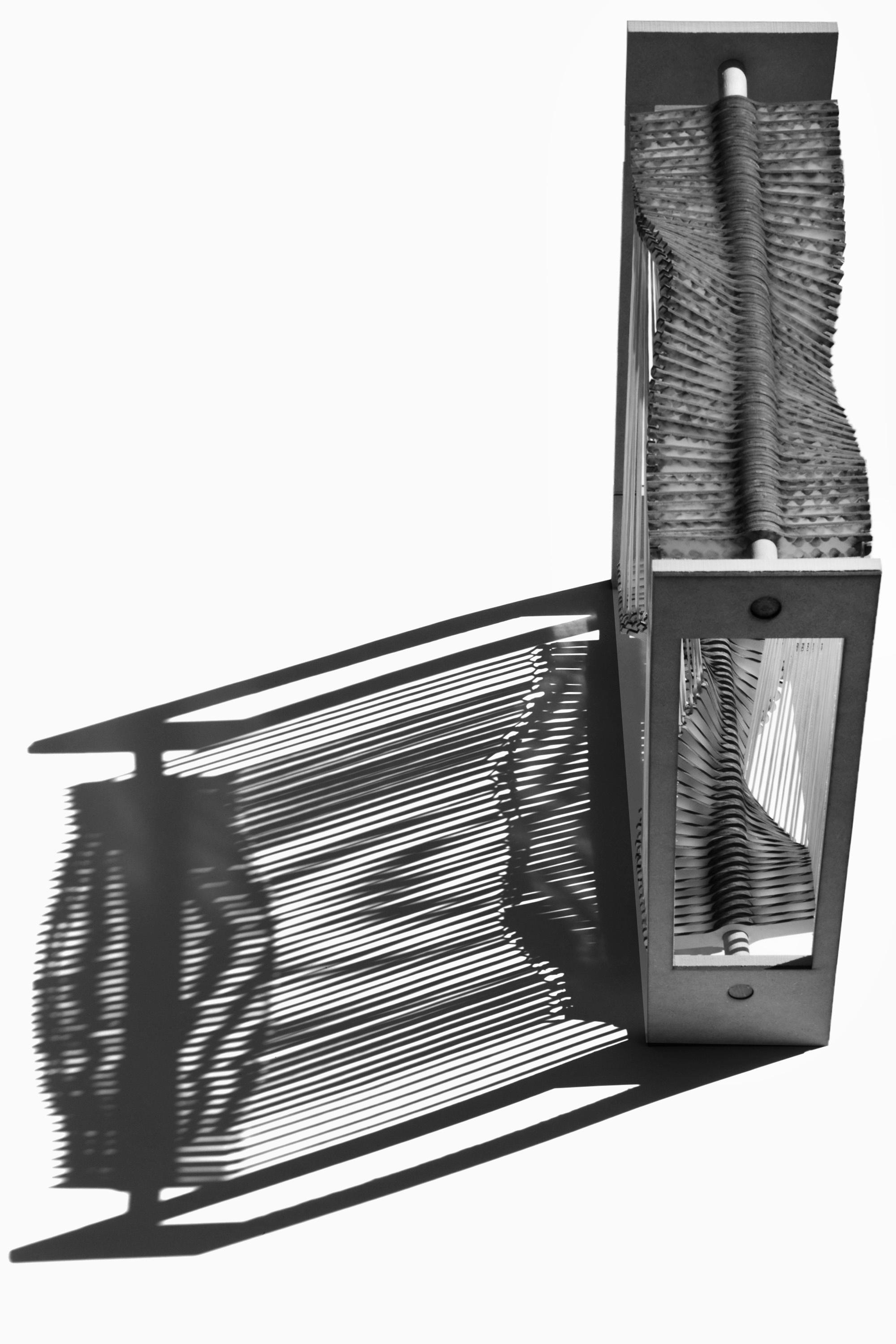
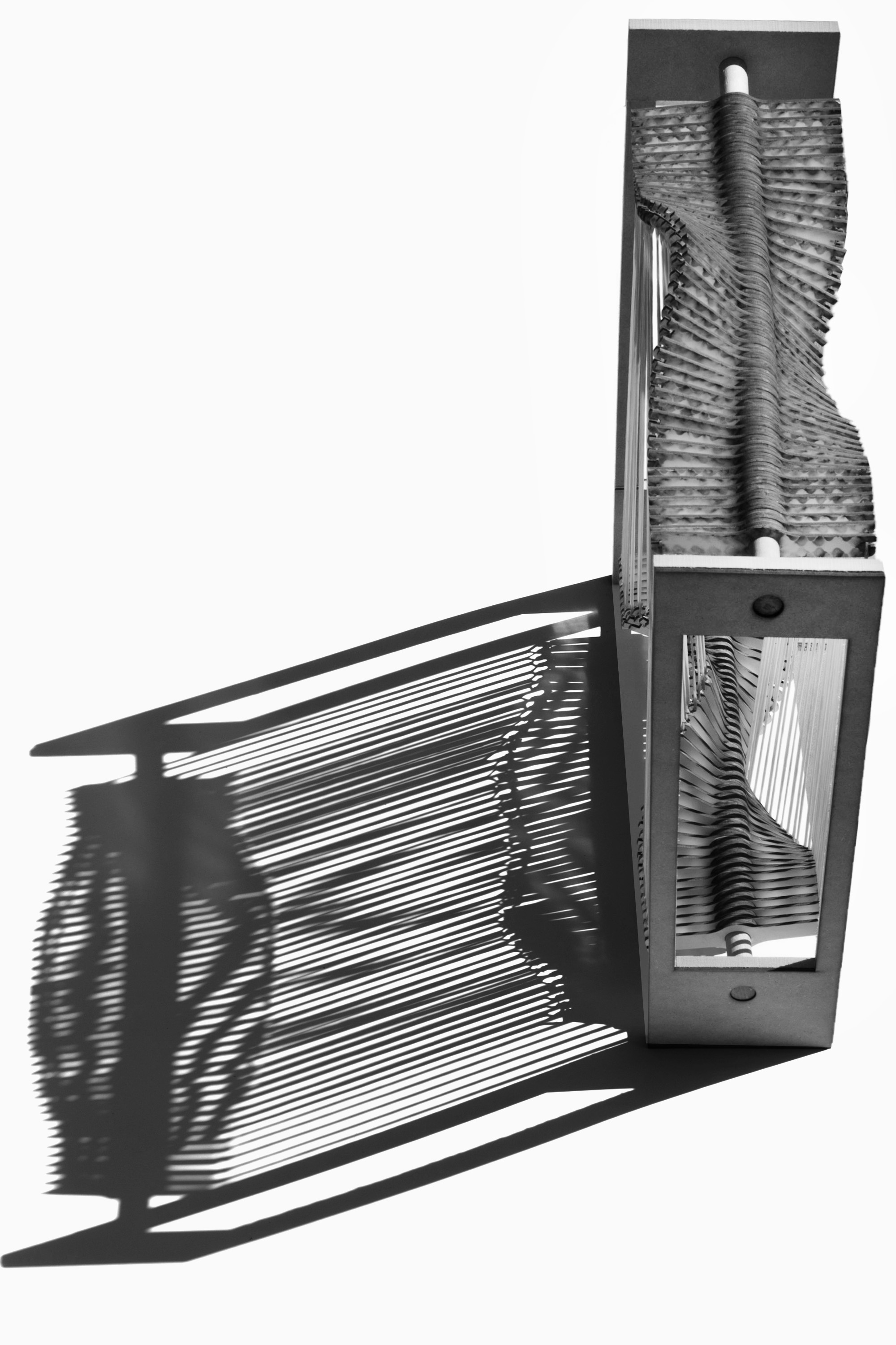
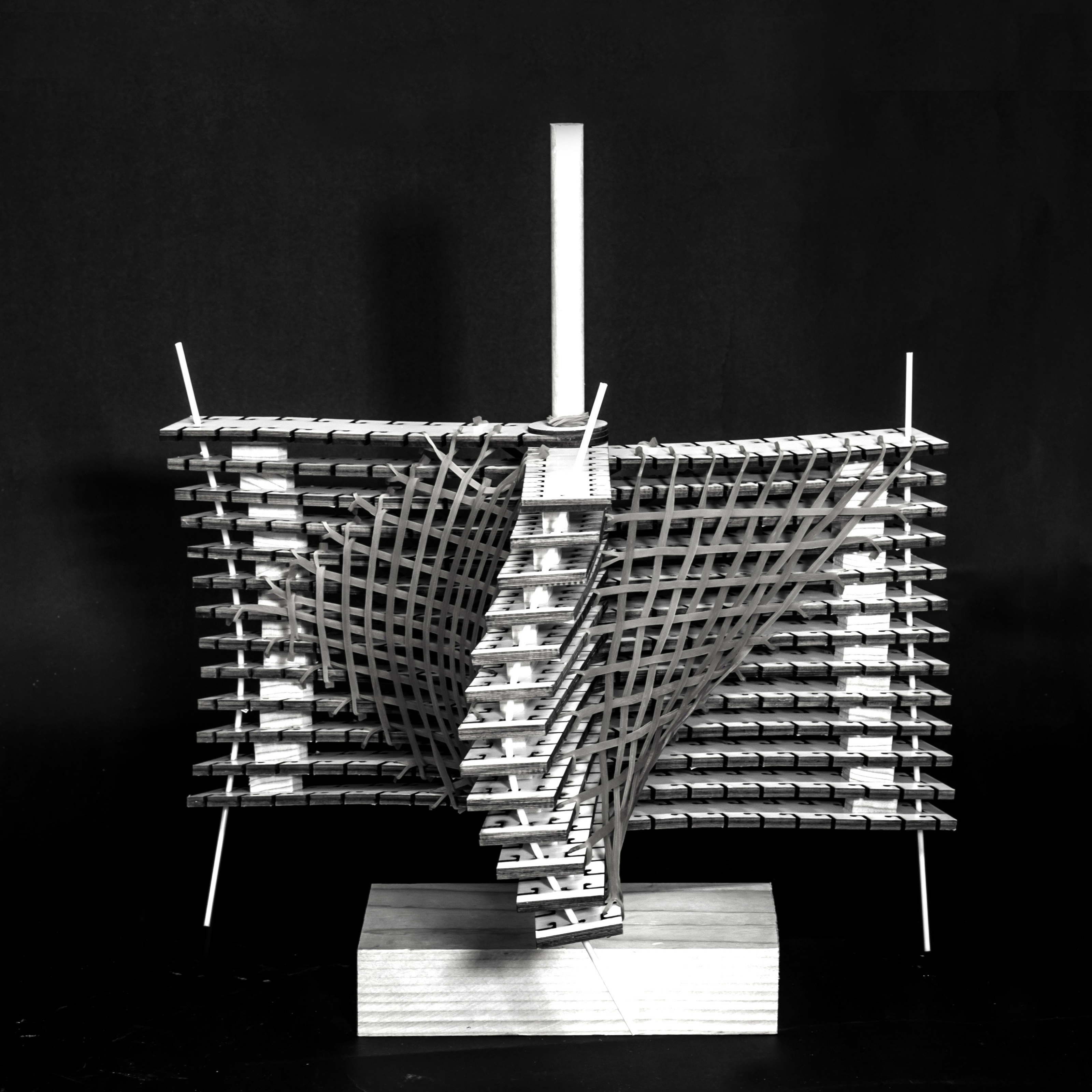
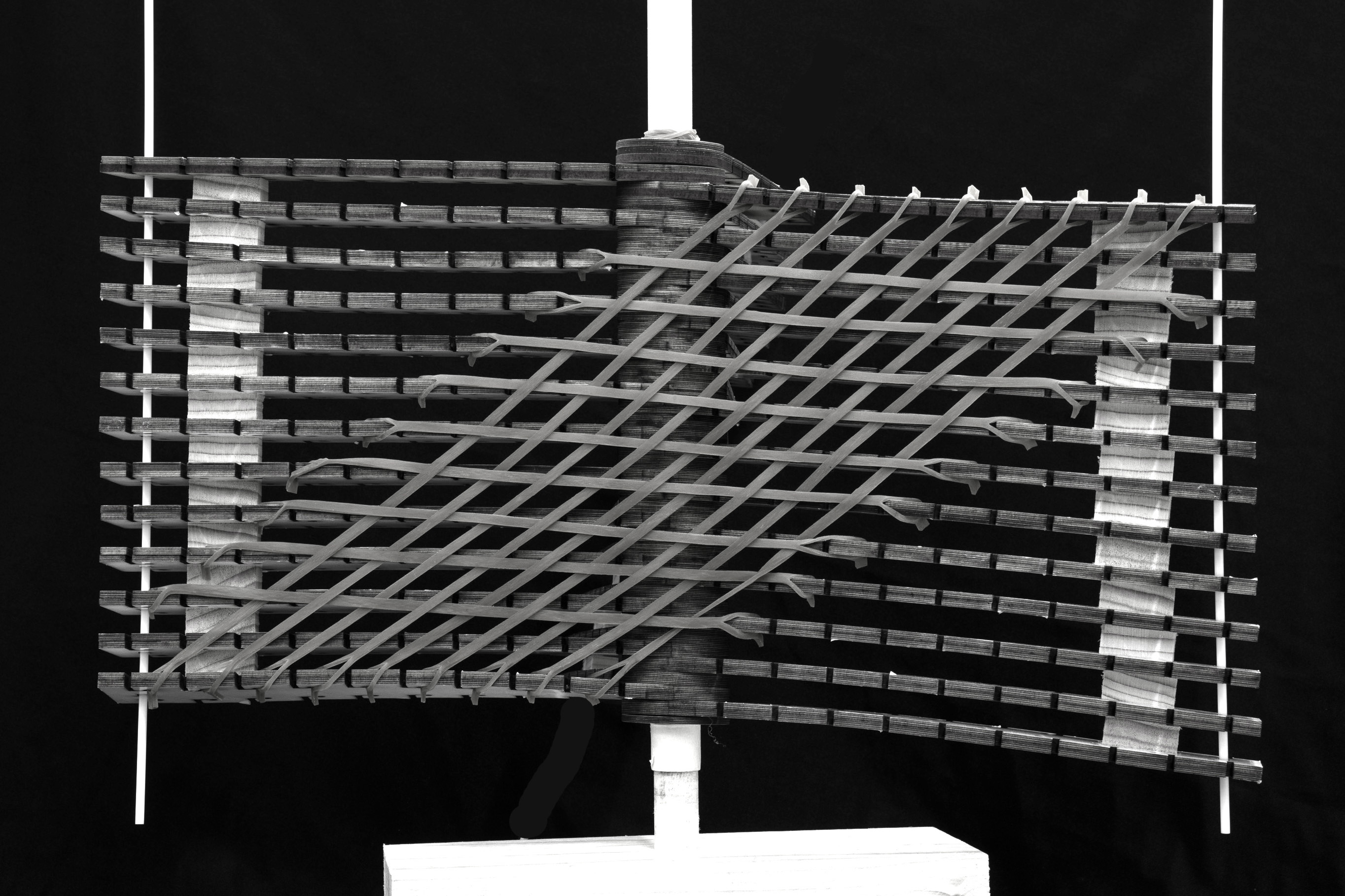
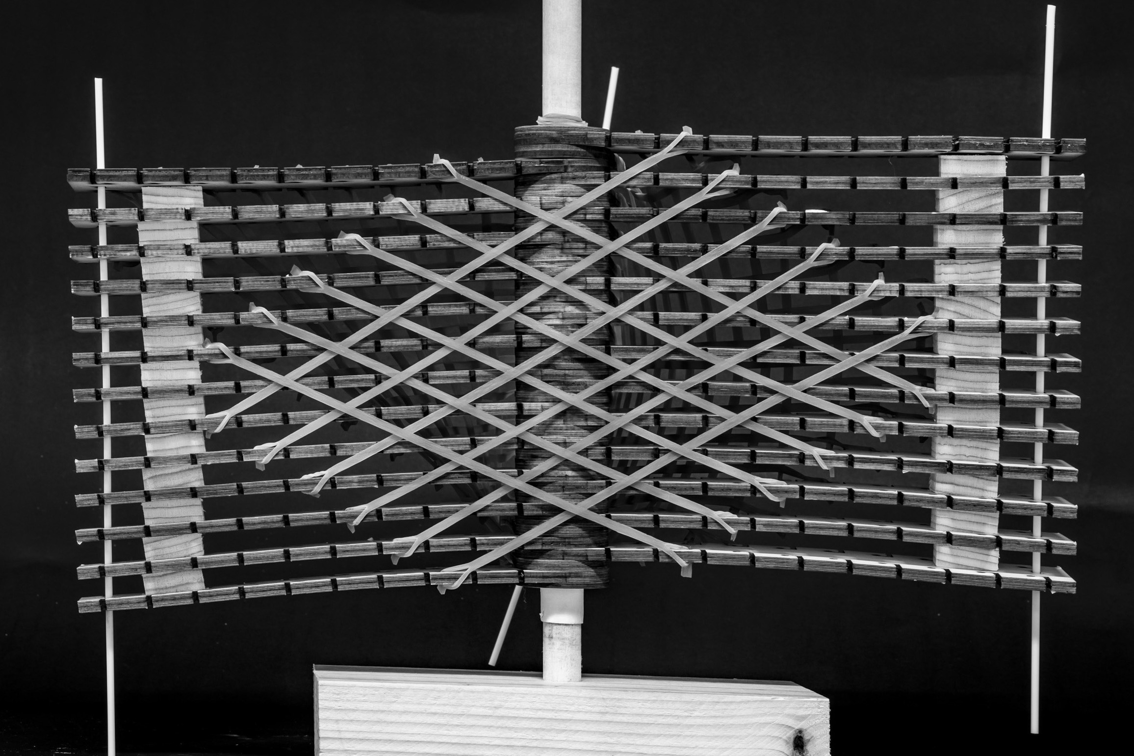
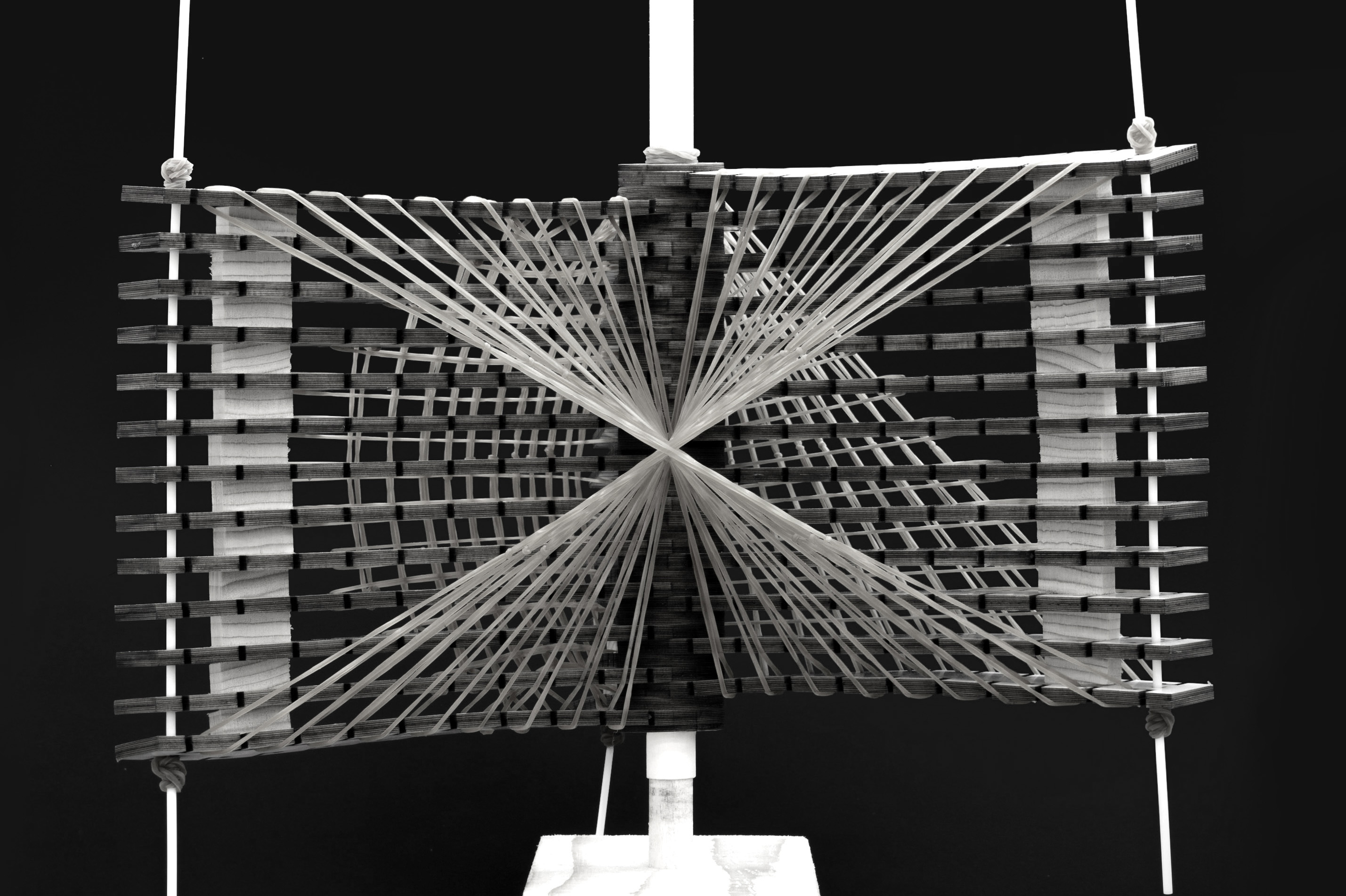
Double Surface Transformation 1
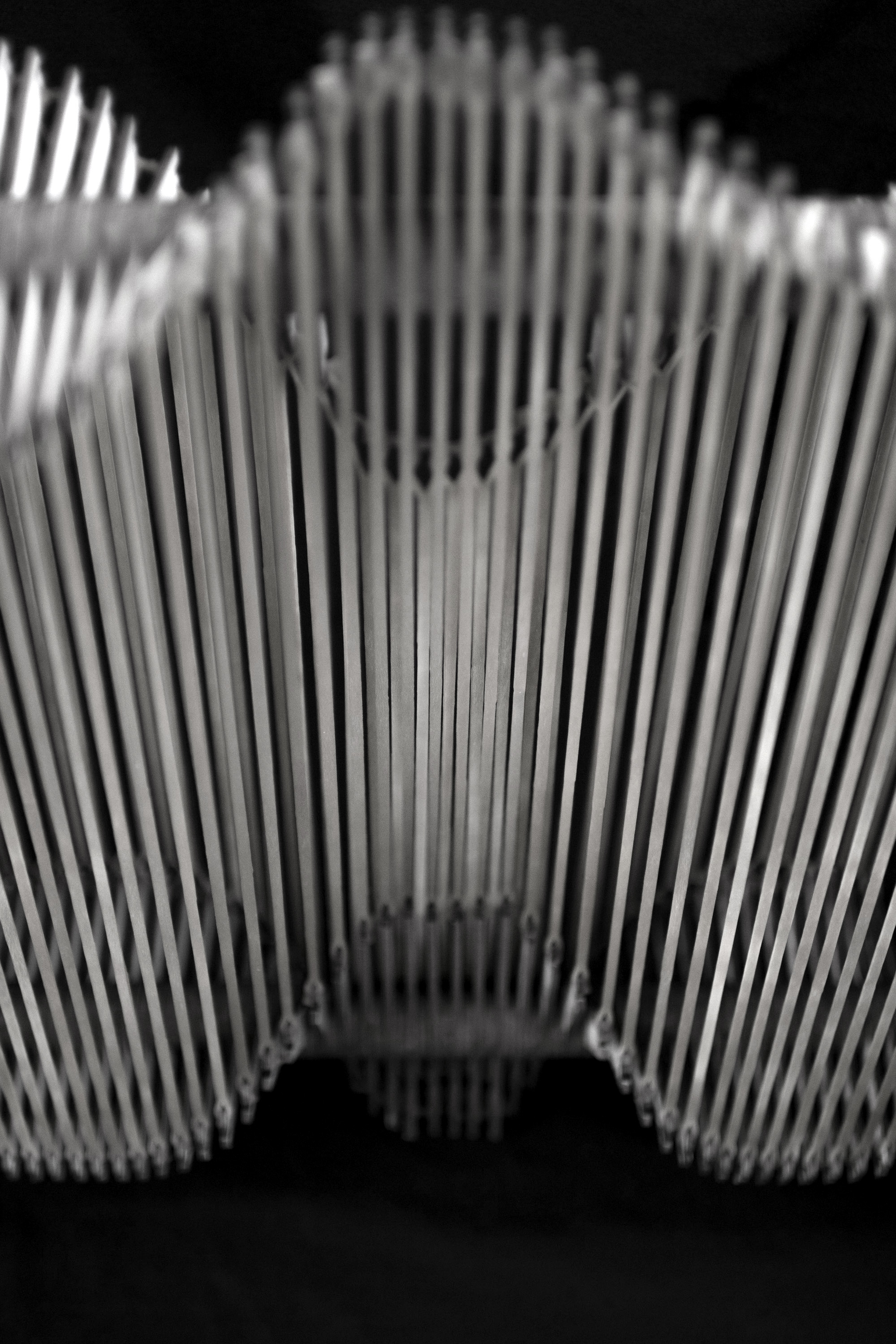
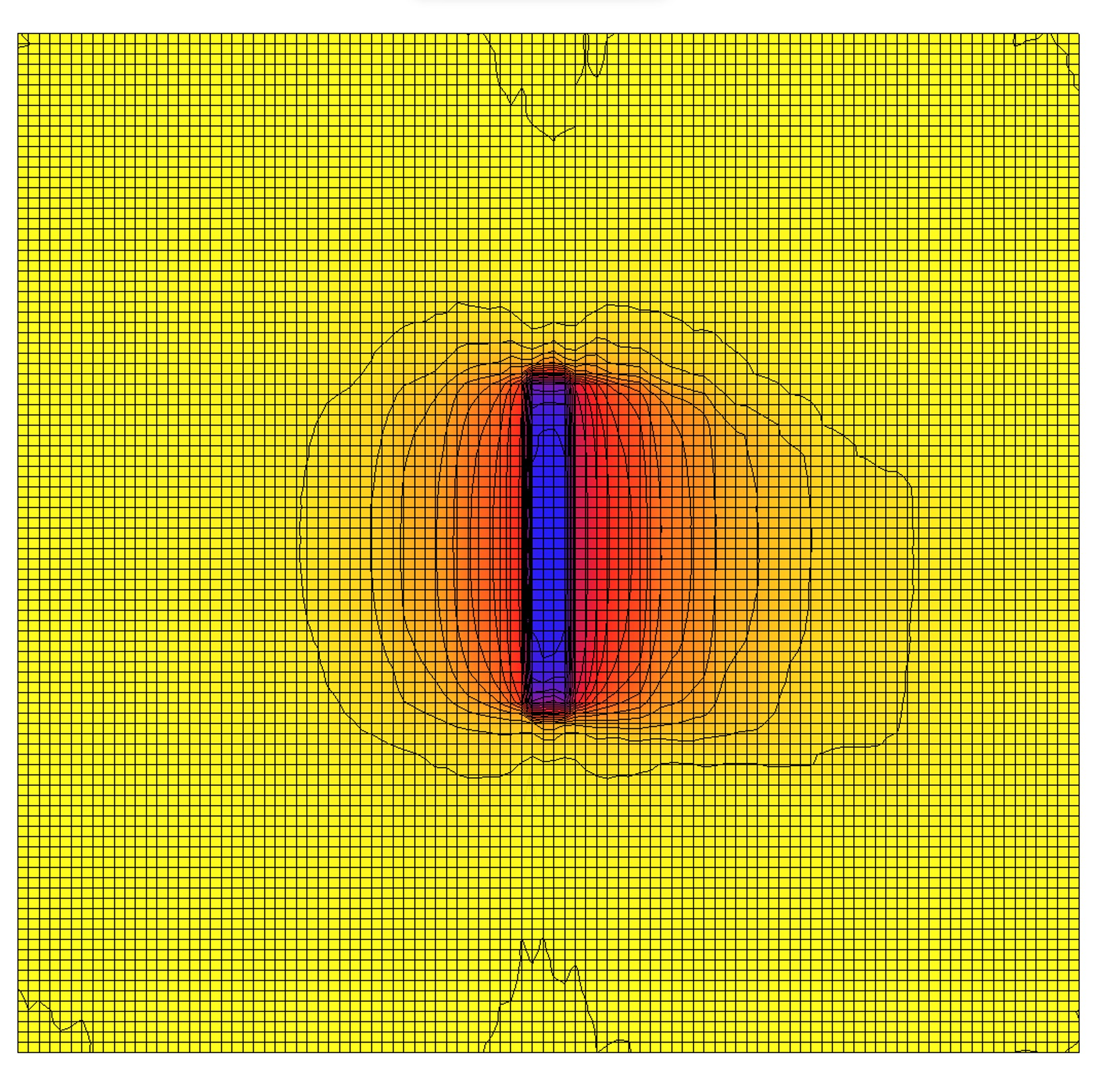
The third model introduces a second layer of fins operating as a distinct surface that transforms independently from the first. The two surfaces are driven by separate actuators, allowing them to create spatial gradients of light and shadow across the panel. At maximum counter-rotation, the two surfaces generate an hourglass-shaped aperture that concentrates shade at the center while opening at the edges. The model was documented from multiple angles to capture the full range of surface interactions; the interior view records the quality of transmitted light, confirming that the interaction of two surfaces produces significantly richer light conditions than a single surface alone.
Model interior
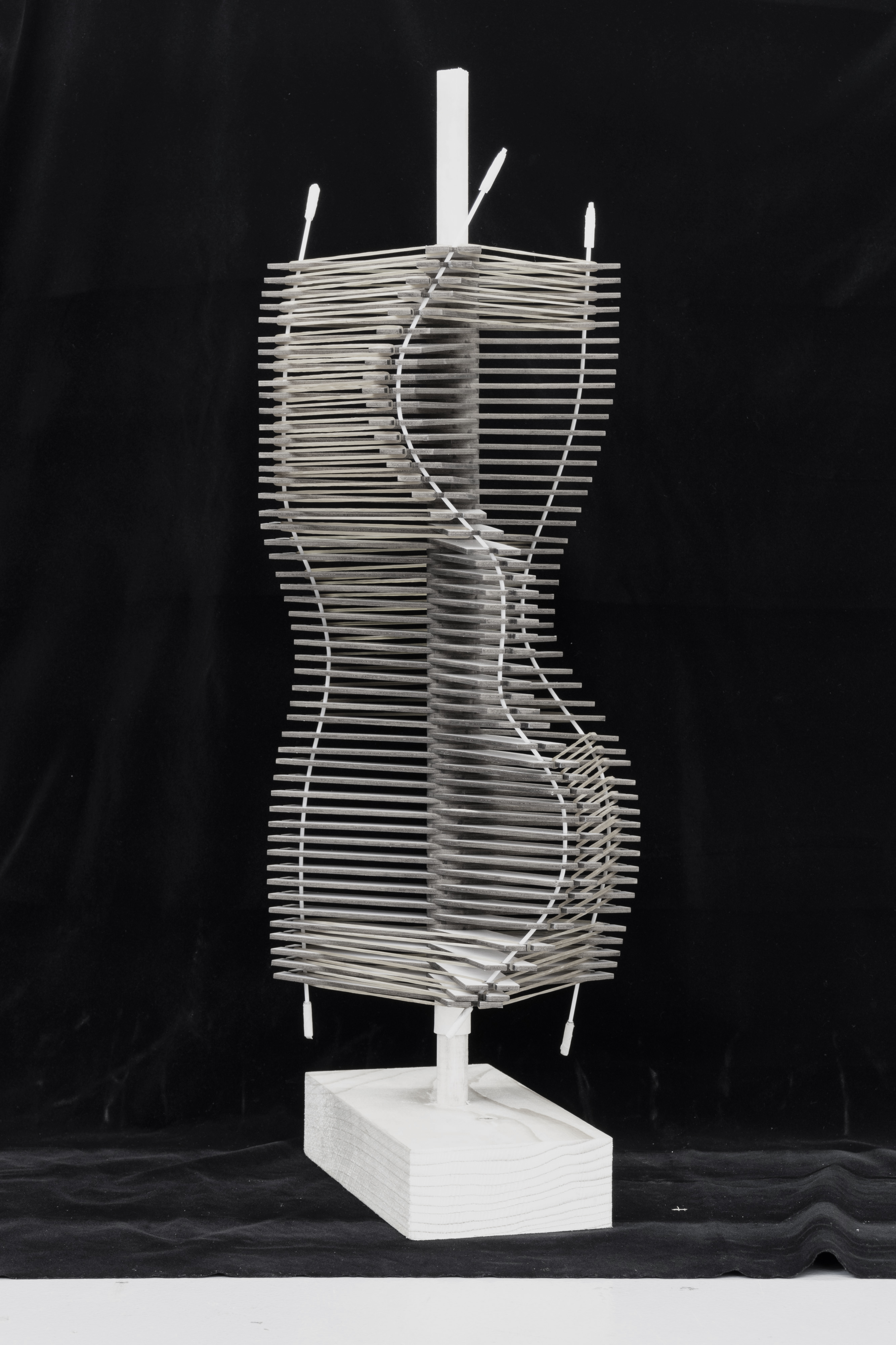
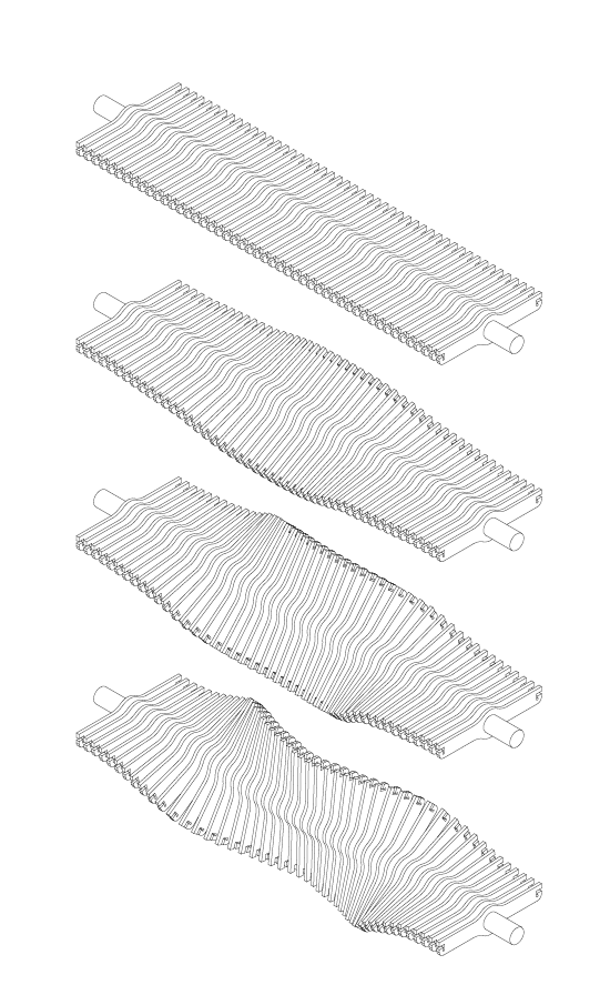
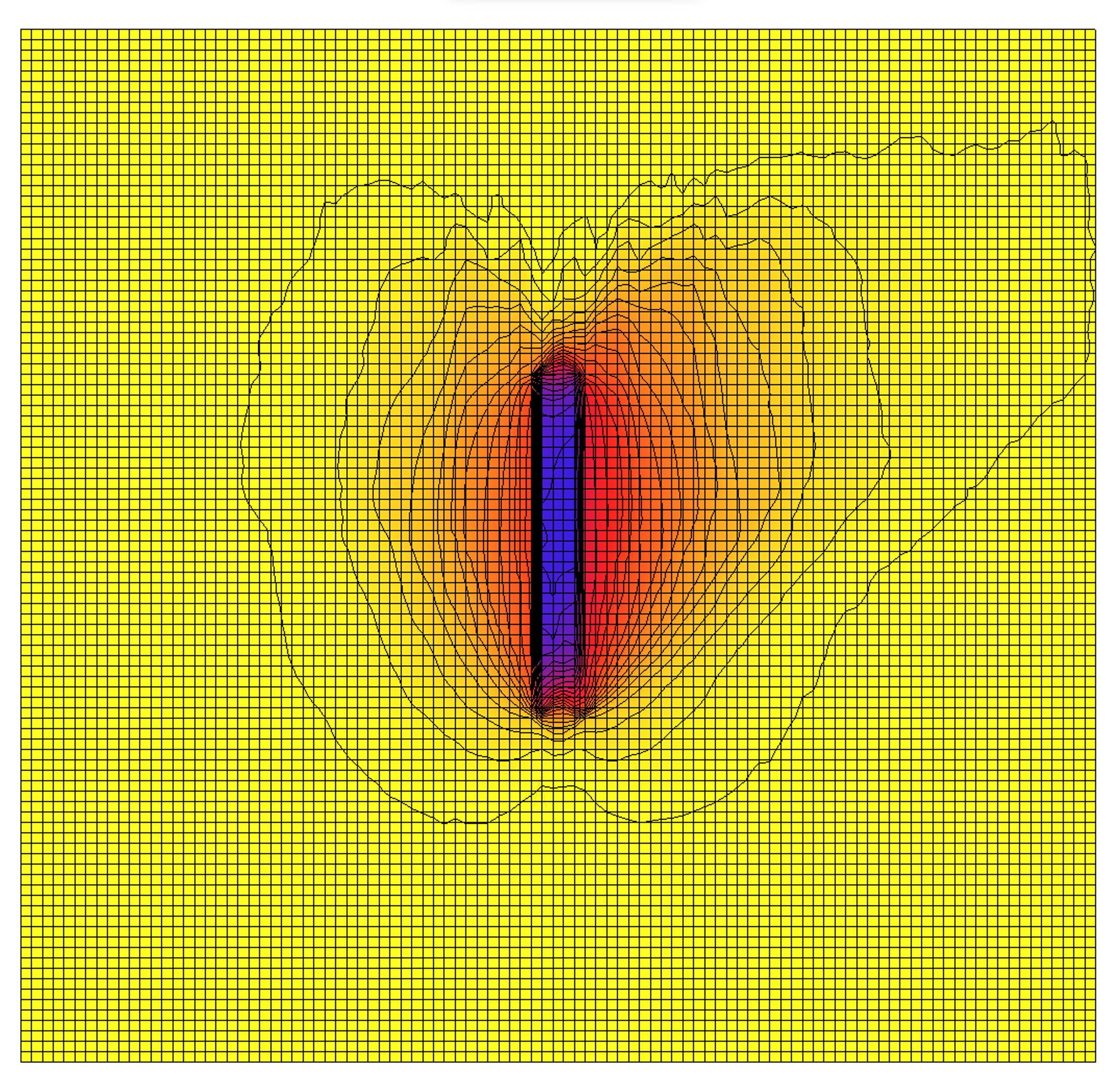
Double Surface Transformation 2
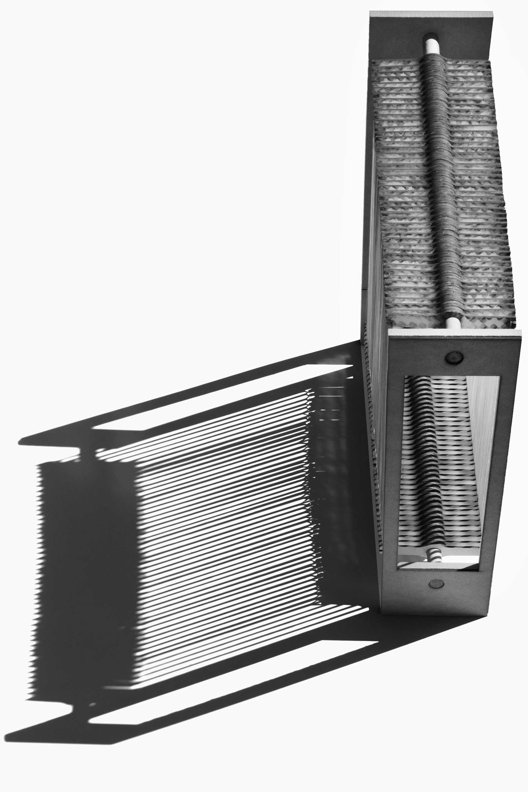
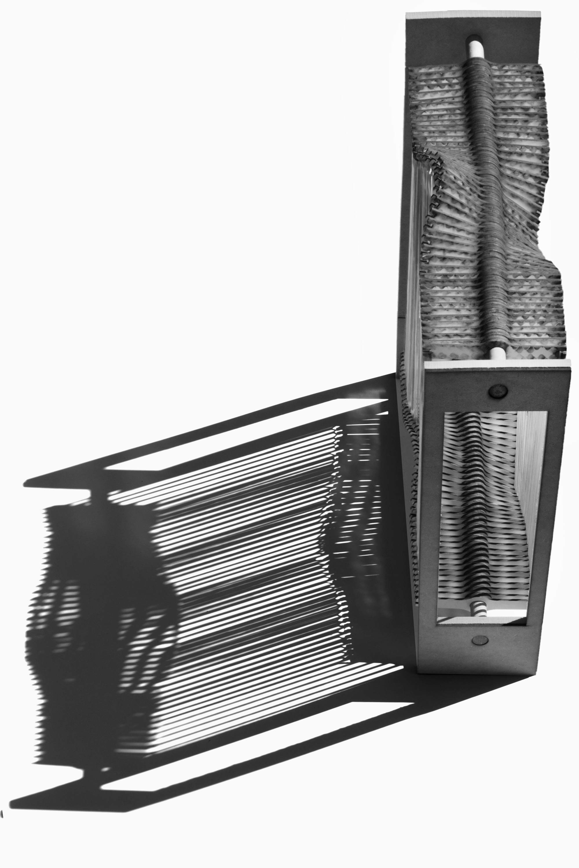
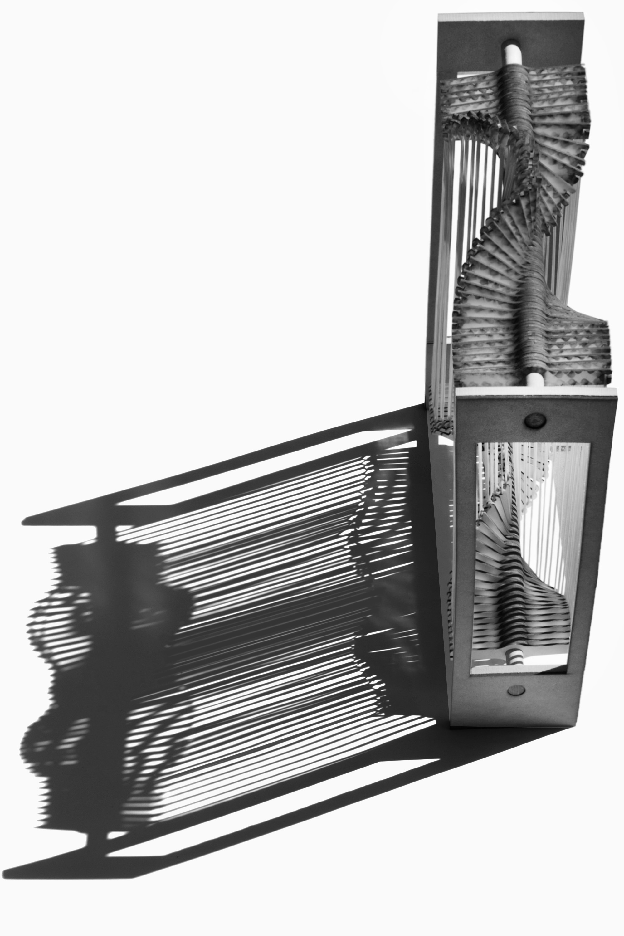
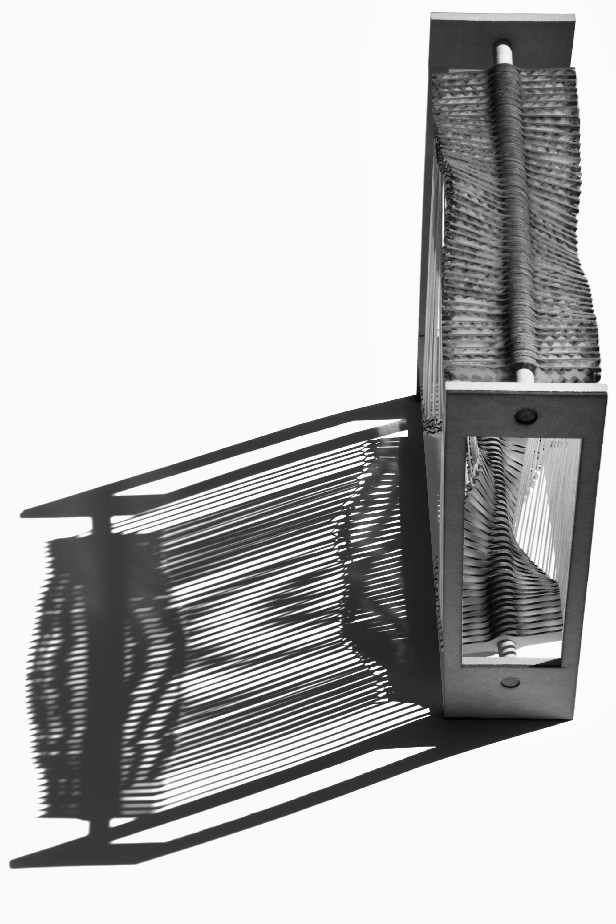
The fourth model introduces wave deformation across the double surface system. Rather than uniform rotation, each fin follows a sinusoidal displacement pattern that propagates across the array, producing a continuously varying aperture gradient. Six wave configurations are documented, ranging from a single broad wave to high-frequency oscillation. The wave pattern is driven computationally: the surface porosity, the ratio of open to closed area, varies continuously over the course of a day as the configuration adapts to the changing solar angle. The analysis diagram documents three representative configurations against sun path polar plots, confirming the system's capacity to track the solar arc from dawn to dusk.
Wave transformation sequence — six configurations
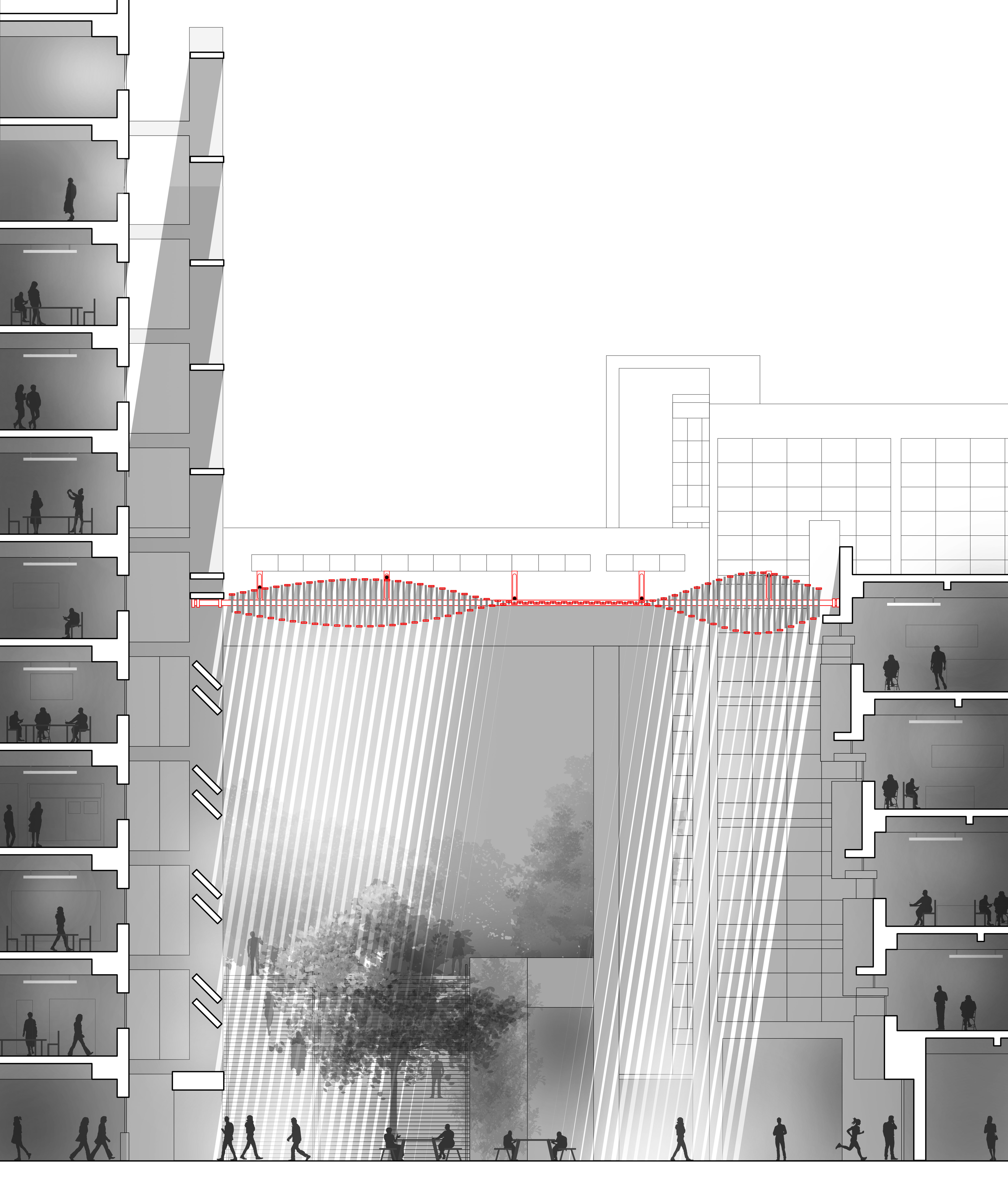
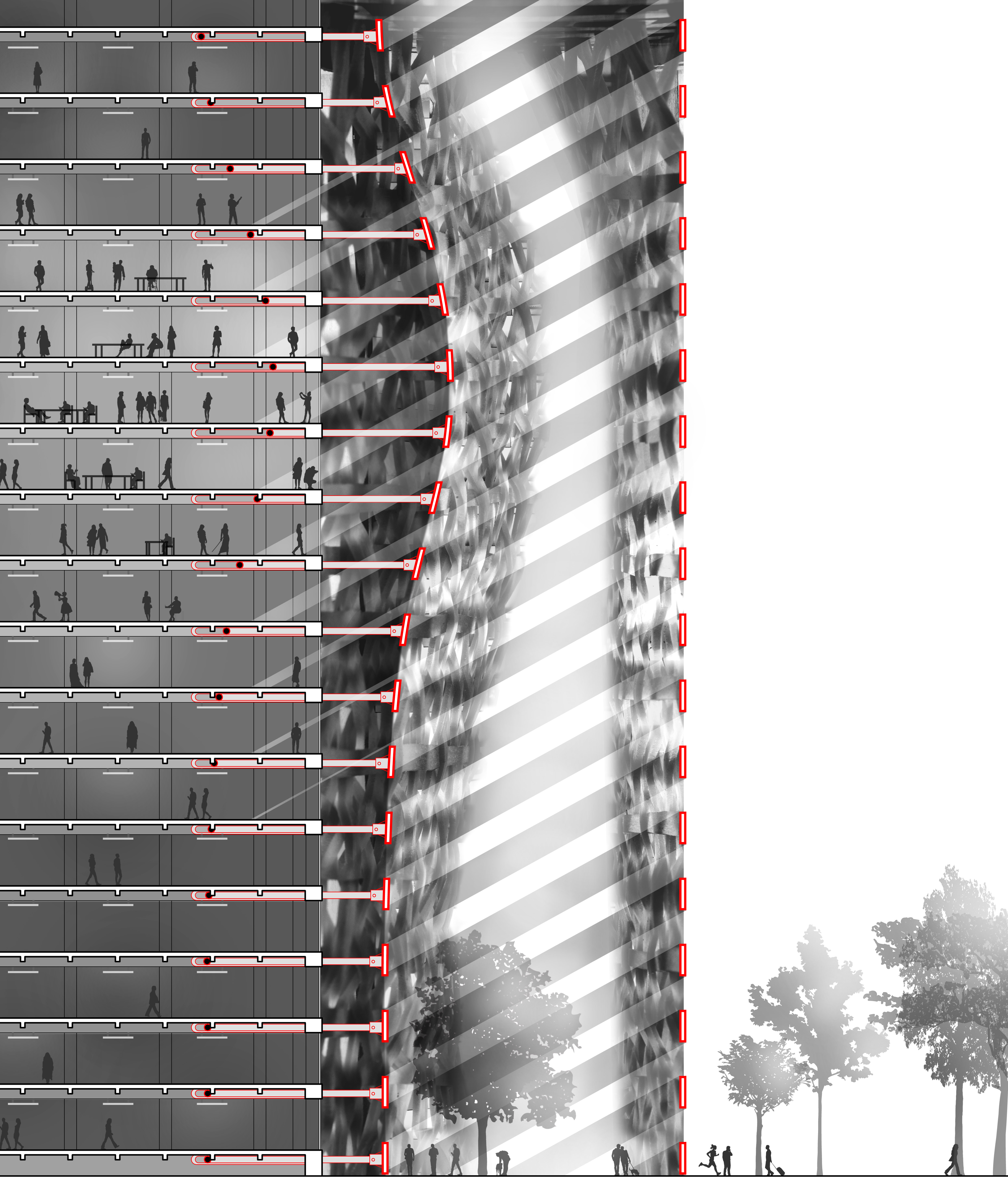
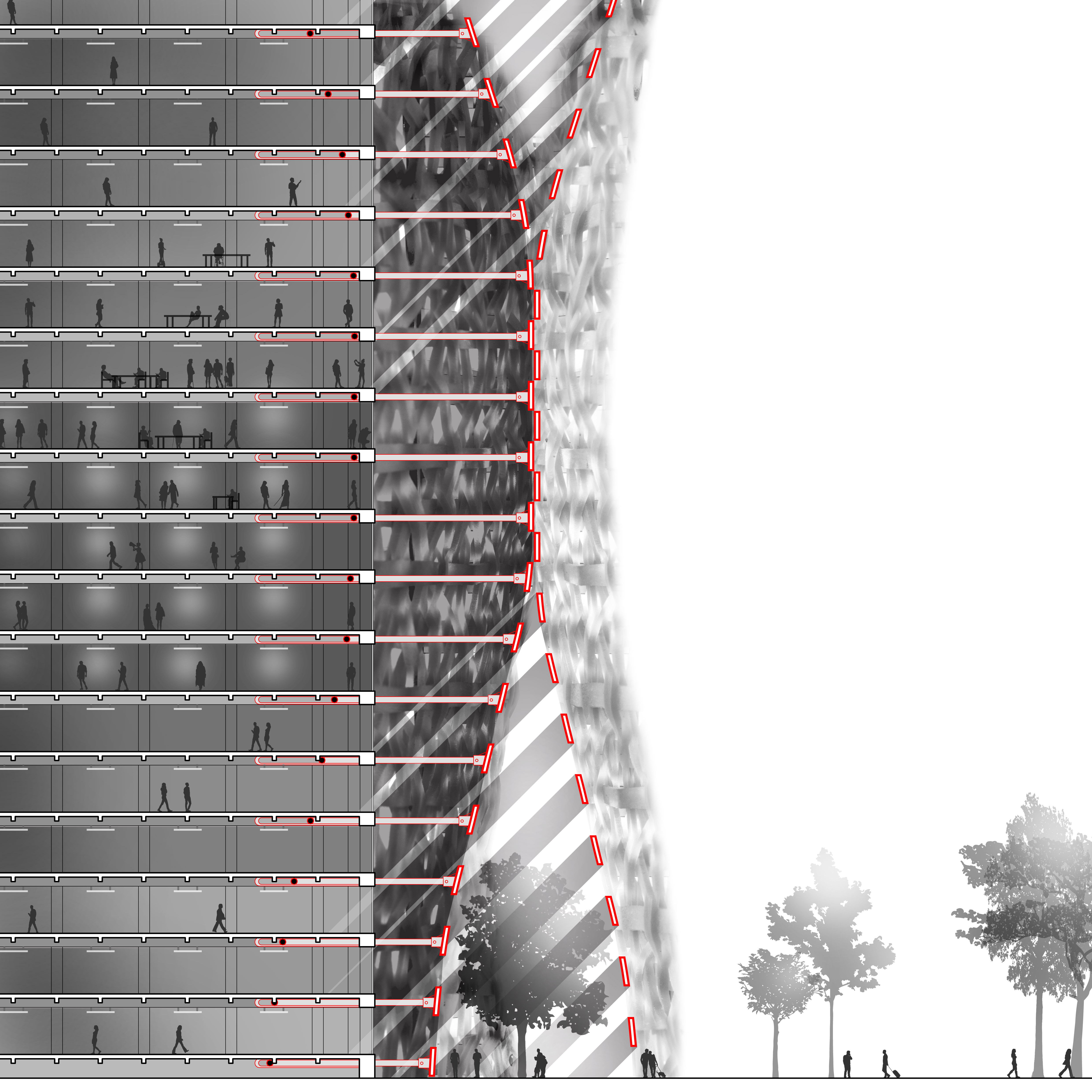
Adaptive Surface in Context
MoiréShade is applied to the south-facing facade of an existing urban building as a full-height adaptive shading screen. Positioned along the building's exterior envelope, the double surface system tracks the arc of the sun across both daily and seasonal cycles. Shadow studies across all four cardinal orientations document the system's dynamic range and its integration with the surrounding urban context.
Seasonal Orientation Analysis
E–W Summer
E–W Winter
N–S Summer
N–S Winter
Cardinal Direction Analysis
Summer East
Summer South
Summer West
Summer North

Winter East
Winter South
Winter West
Winter North
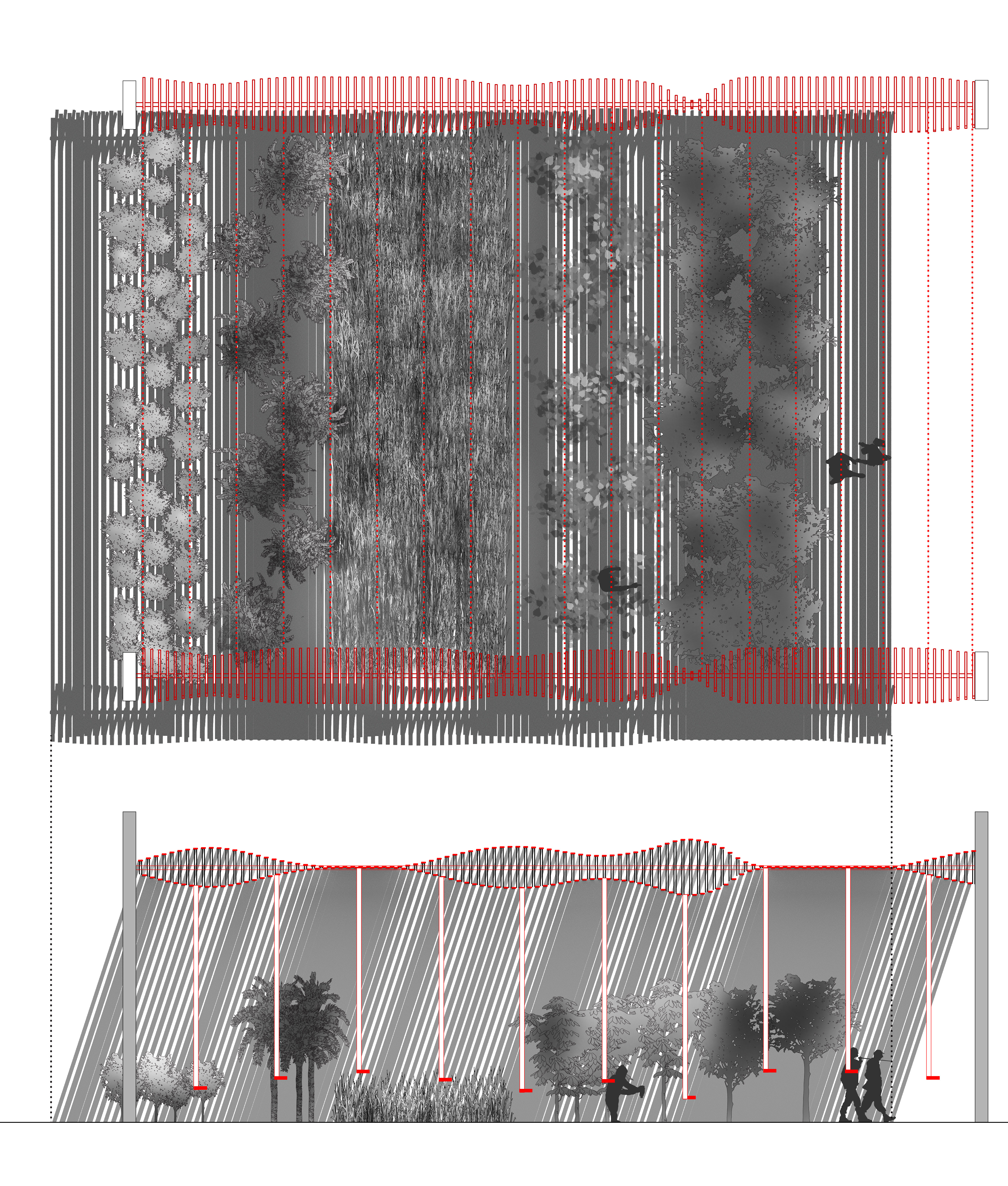
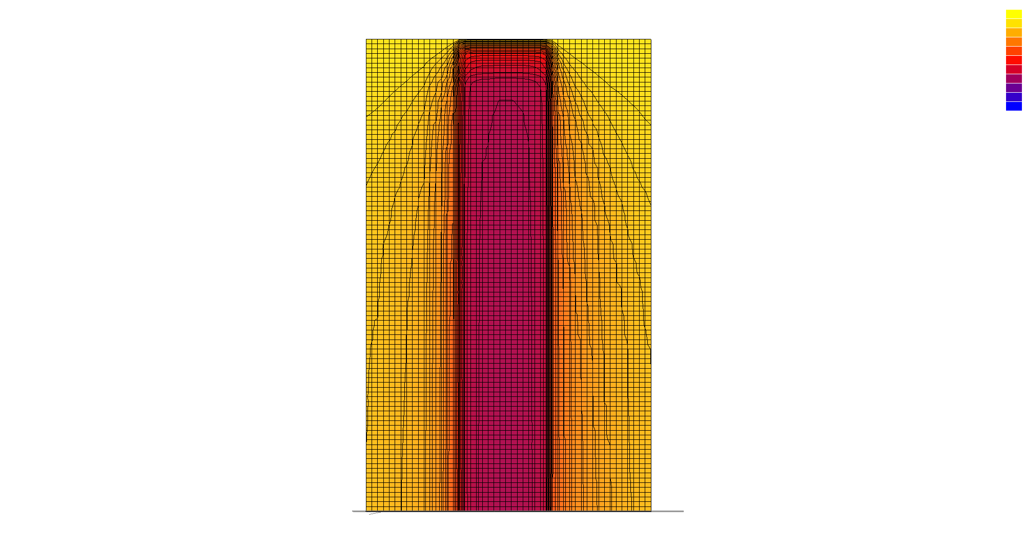
Vertical Shading in Open Field
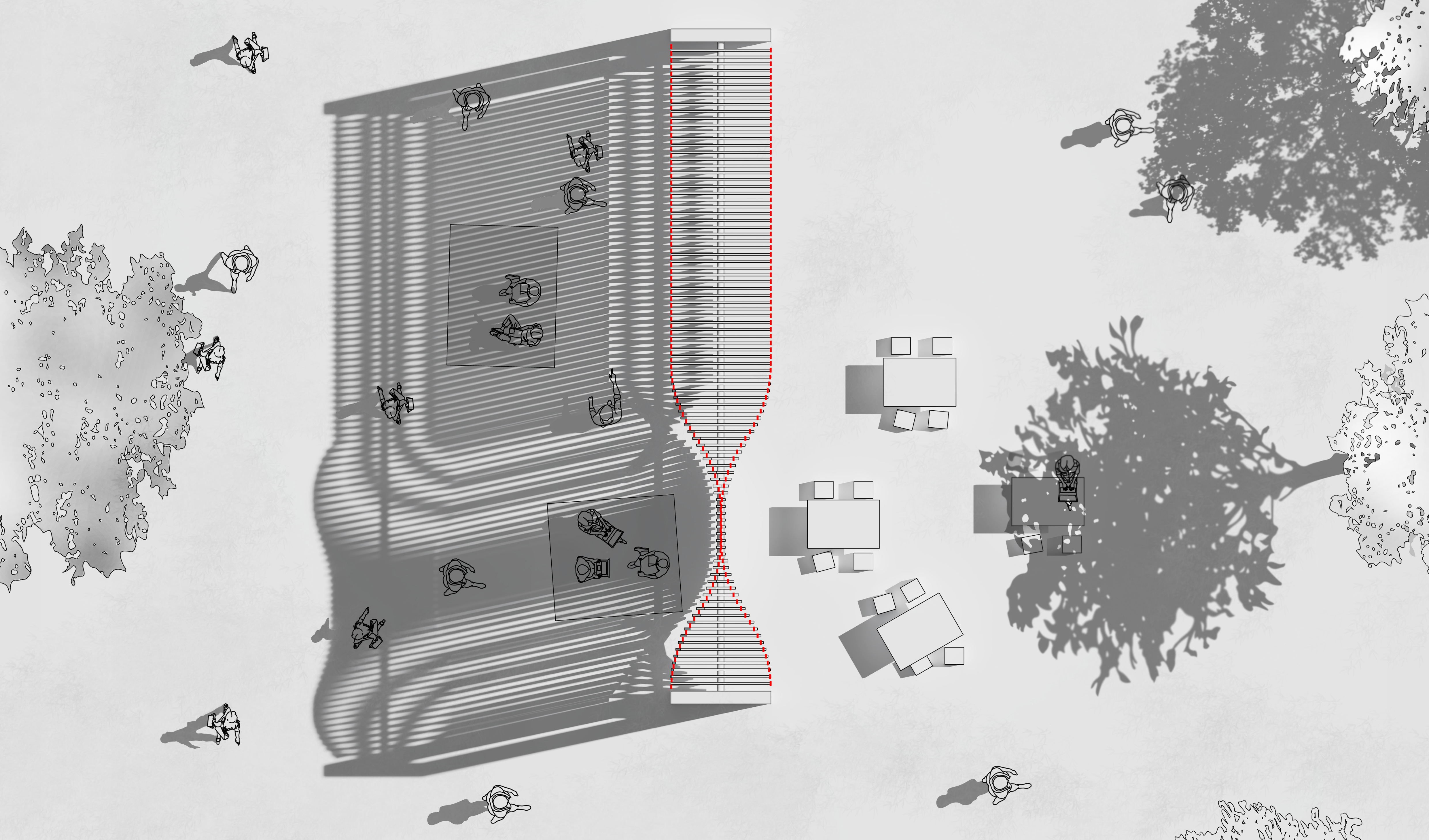
9:00 AM — low sun angle, east-biased shadow
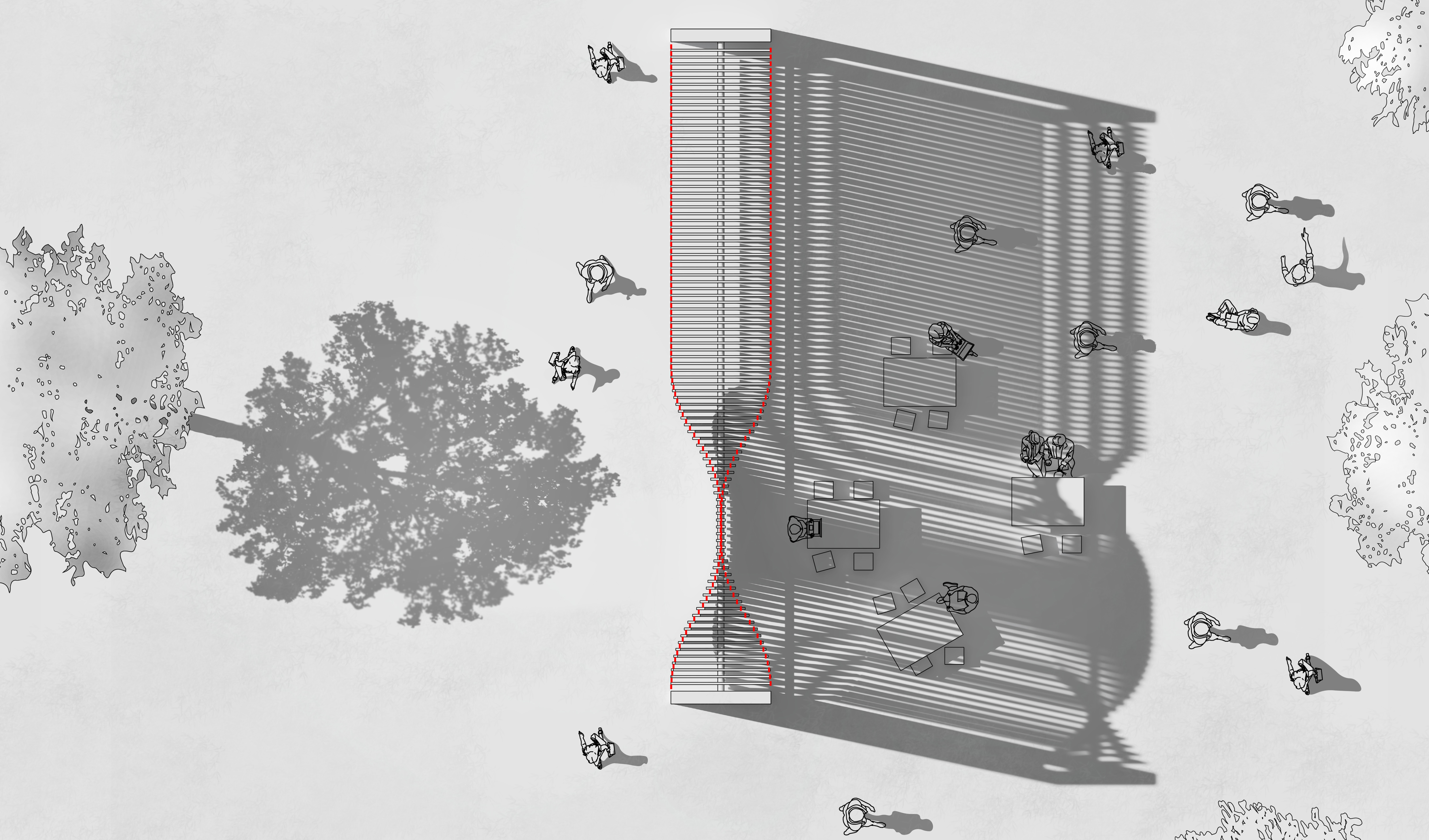
4:00 PM — descending sun, west-biased shadow
Horizontal Shading Above Courtyard
Vertical Shading as Facade